Distributed illumination system

a distribution system and illumination technology, applied in the direction of lighting support devices, light source combinations, instruments, etc., can solve the problems of ineffective general application, inefficiency and inefficient dimming of conventional light bulb types in common practice, so as to improve the aesthetics of overhead lighting, the physical infrastructure of overhead lighting is significantly simplified, and the look and feel of overhead lighting systems around the world have not changed appreciably

Active Publication Date: 2014-03-18
SNAPTRACK
View PDF298 Cites 40 Cited by
  • Summary
  • Abstract
  • Description
  • Claims
  • Application Information

AI Technical Summary

Benefits of technology

[0017]The present invention introduces common thin tile-like building materials that are embedded with thin tile-like and directionally illuminating lighting engines, the means to access power for this lighting and the means to control this lighting. While most examples of this invention are aimed at overhead lighting, usage extends to a wider range of thin-profile building materials commonly used in ceilings and walls. Such multifunctional lighting materials will be shown as introducing a new generation of energy conservation options especially for the commercial overhead lighting systems they replace, as extending the range of overhead lighting design options available to lighting architects, and as providing a more efficient means of overhead lighting manufacturing and installation. By embedding both lighting and the control of lighting within otherwise common building materials, the physical infrastructures in overhead lighting are significantly simplified, as are the corresponding commercial lighting distribution procedures. Moreover, rather than deploying only groups of large powerful lighting fixtures, the distributed approach described by the present invention enables some substantial improvements in the aesthetic qualities of overhead lighting not possible with standard practice.

Problems solved by technology

However, the general look, feel and physical construction of overhead ceiling lighting systems around the world have not changed appreciably in the last 50 years.
Industrial overhead lighting, whether in high-rise office buildings, factories, or industrial office parks has been and still is typified by regular lines of cumbersome high power down lighting fixtures mounted within (or hanging through) openings or clearances made in the lightweight decorative (sound absorbing) ceiling panels surrounding them.
High voltage (ac) electrical power is applied to large groups of these high light output lighting fixtures at the same time using expensive high voltage cabling and conduits.
Energy waste due to fixture inefficiency and their substantial amounts of misdirected light is enormous.
Dimming the conventional light bulb types that are in common practice is inefficient, and not generally applied, cutting off an attractive means of energy conservation.
No remotely similar system is deployable using conventional lighting practices and conventional lighting hardware.
Ceiling panel materials are typically 0.5-0.75 inches thick and quite fragile in their construction.
Classical lighting fixtures and luminaires are simply too thick and too heavy to be embedded in such materials, whether at time of manufacture or installation.
Embedding high voltage power lines in conventional ceiling material is discouraged by Governmental safety regulations and by incompatibilities in the way the classical lighting fixtures are installed and mounted.
As it's turning out, however, the early LED fixture substitutions are only somewhat lighter in weight and only somewhat more compact than their traditionally cumbersome light bulb counterparts.
Not only would light emission spread undesirably in all angular directions, but also LED brightness would simply be too high to risk human exposure to accidental direct view.
While doing so is described in some detail below, no known prior art arrangements adequately mask direct view of the LEDs' extraordinarily high brightness level (sometimes 200 times greater than the brightest commercially available light bulb fixture) without destroying the LEDs' corresponding energy efficiency, creating off-angle glare, or both.

Method used


Image

  • Distributed illumination system
  • Distributed illumination system
  • Distributed illumination system

Examples


Embodiment Construction

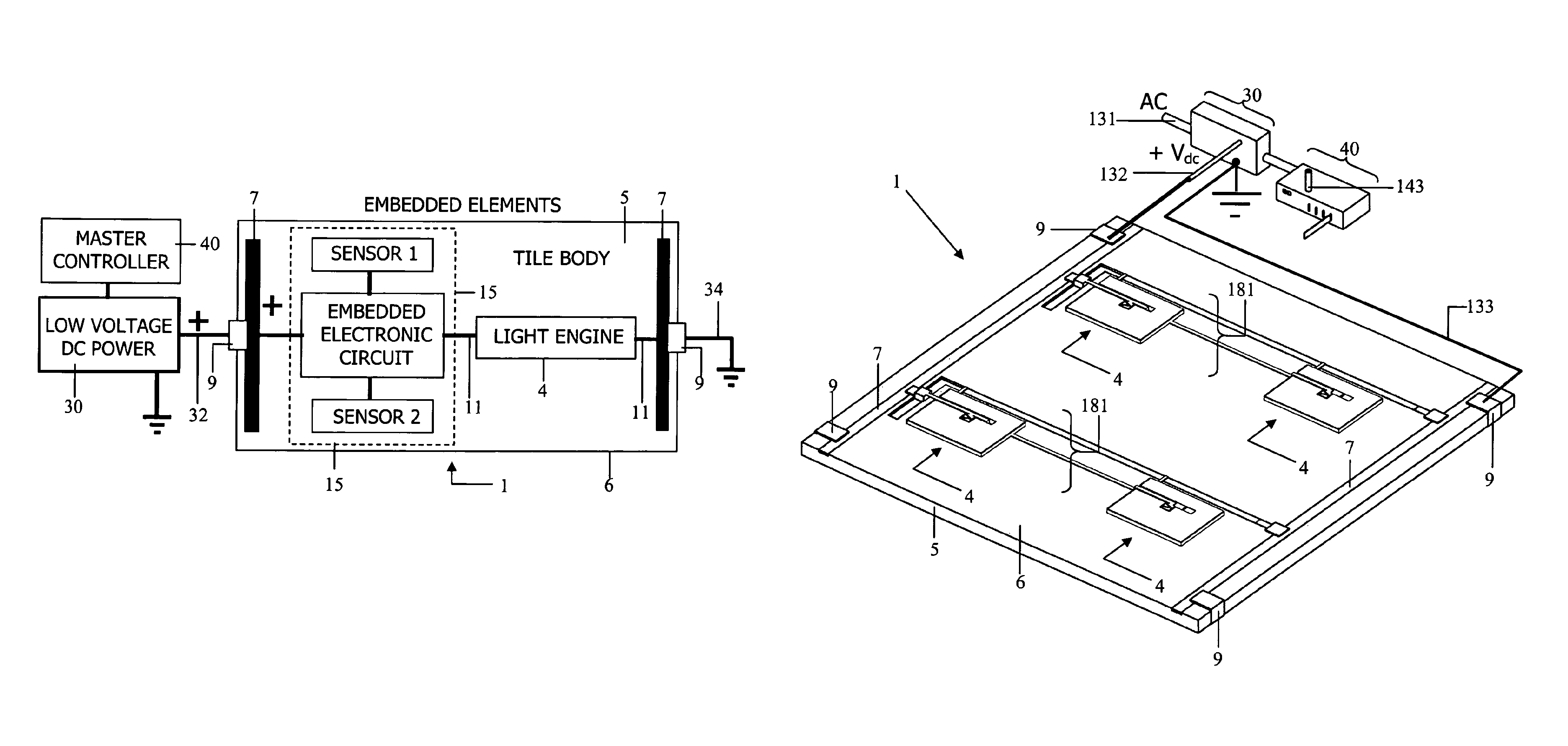
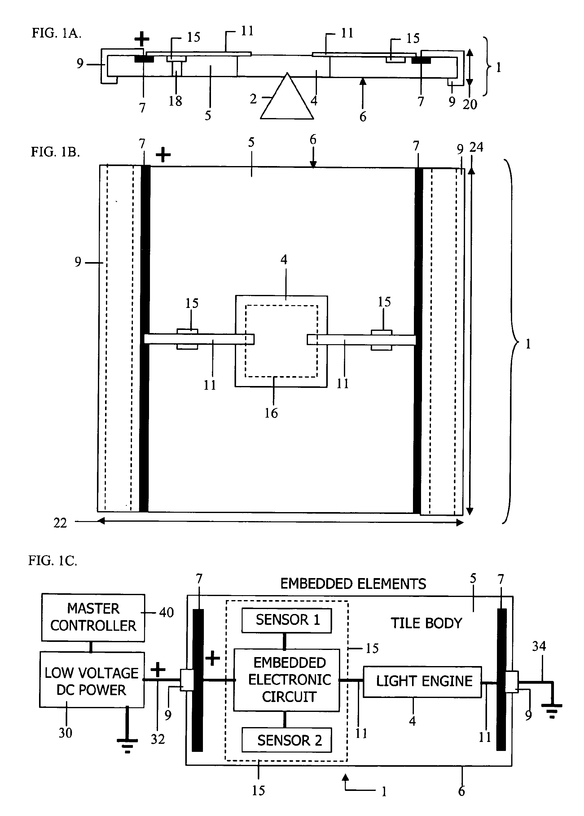
[0225]An optical system 1 constructed in accordance with the distributed overhead illumination system invention is shown in a generalized side view, FIG. 1A, in a generalized top view, FIG. 1B, and in a generalized block diagram form of electrical circuit schematic, FIG. 1C. For purposes of scaling, the cross-sectional thickness 20 of system 1 in FIG. 1A may be visualized as being 0.75 inches, and the edge boundaries 22 and 24 of system 1 in FIG. 1B may be visualized as being 2 feet by 2 feet square. In general, thickness 20 may vary between 0.25 inches and 1.5 inches, and edge boundaries 22 and 24 may vary between about 1-foot and about 6-feet, with the nominal dimensional combinations 2 feet by 2 feet and 2 feet by 4 feet being most popular among commercial standards. Within this description, all of the examples illustratively describe 24″×24″ panel materials, most often referred to a “tile.” In addition, all of the ceiling illumination examples provided below anticipate use in su...


PUM


Abstract

The present invention introduces a new class of lightweight tile-based illumination systems for uses wherein thin directionally-illuminating light distributing engines are embedded into the body of otherwise standard building materials like conventional ceiling tiles along with associated means of electrical control and electrical power interconnection. As a new class of composite light emitting ceiling materials, the present invention enables a lighter weight more flexibly distributed overhead lighting system alternatives for commercial office buildings and residential housing without changing the existing materials. One or more spot lighting, task lighting, flood lighting and wall washing elements having cross-sectional thickness matched to that of the building material or tile into which they are embedded, are contained and interconnected within the material body's cross-section. Embedded power control devices interconnected to each lighting element in the distributed system communicate with a central switching center that thereby controls each light-emitting element in the system.

Description

CROSS-REFERENCE TO RELATED APPLICATIONS[0001]This application is a continuation of International Application No. PCT / US2009 / 005555, filed Oct. 8, 2009, which claims the benefit of U.S. Provisional Application No. 61 / 104,606, filed Oct. 10, 2008. The disclosures of all of the above-referenced prior applications are considered part of, and are incorporated by reference in, this disclosure.BACKGROUND OF THE INVENTION[0002]This section is intended to provide a background or context to the invention that is, inter alia, recited in the claims. The description herein may include concepts that could be pursued, but are not necessarily ones that have been previously conceived or pursued. Therefore, unless otherwise indicated herein, what is described in this section is not prior art to the description and claims in this application and is not admitted to be prior art by inclusion in this section.[0003]For industrial, commercial, and residential applications, consumers demand more complicated...

Claims


Application Information

Patent Timeline
Patent Type & Authority Patents(United States)
IPC IPC(8): H05B37/02G05F1/00
CPCE04B9/32F21S2/00F21S8/026F21V21/002F21V33/006H05B37/029F21V29/74F21Y2113/00F21Y2115/10F21V29/004H05B47/155F21V17/00
Inventor HOLMAN, ROBERT L.SAMPSELL, MATTHEW B.SAMPSELL, JEFFREY B.
Owner SNAPTRACK
Why Eureka
Try Eureka