Optically transduced MEMS magnetometer

a magnetometer and optical transducer technology, applied in the field of micro electromechanical system (mems) sensors, can solve the problems of inability to achieve dynamic range, inability to detect the magnetic field, inherent sensitivity and other limitations of conventional sensing techniques, etc., and achieve the effects of increasing conductive cross-section, increasing dimensional mass, and increasing out-of-plane rigidity

Active Publication Date: 2014-03-18
NAT TECH & ENG SOLUTIONS OF SANDIA LLC
View PDF5 Cites 29 Cited by
  • Summary
  • Abstract
  • Description
  • Claims
  • Application Information

AI Technical Summary

Benefits of technology

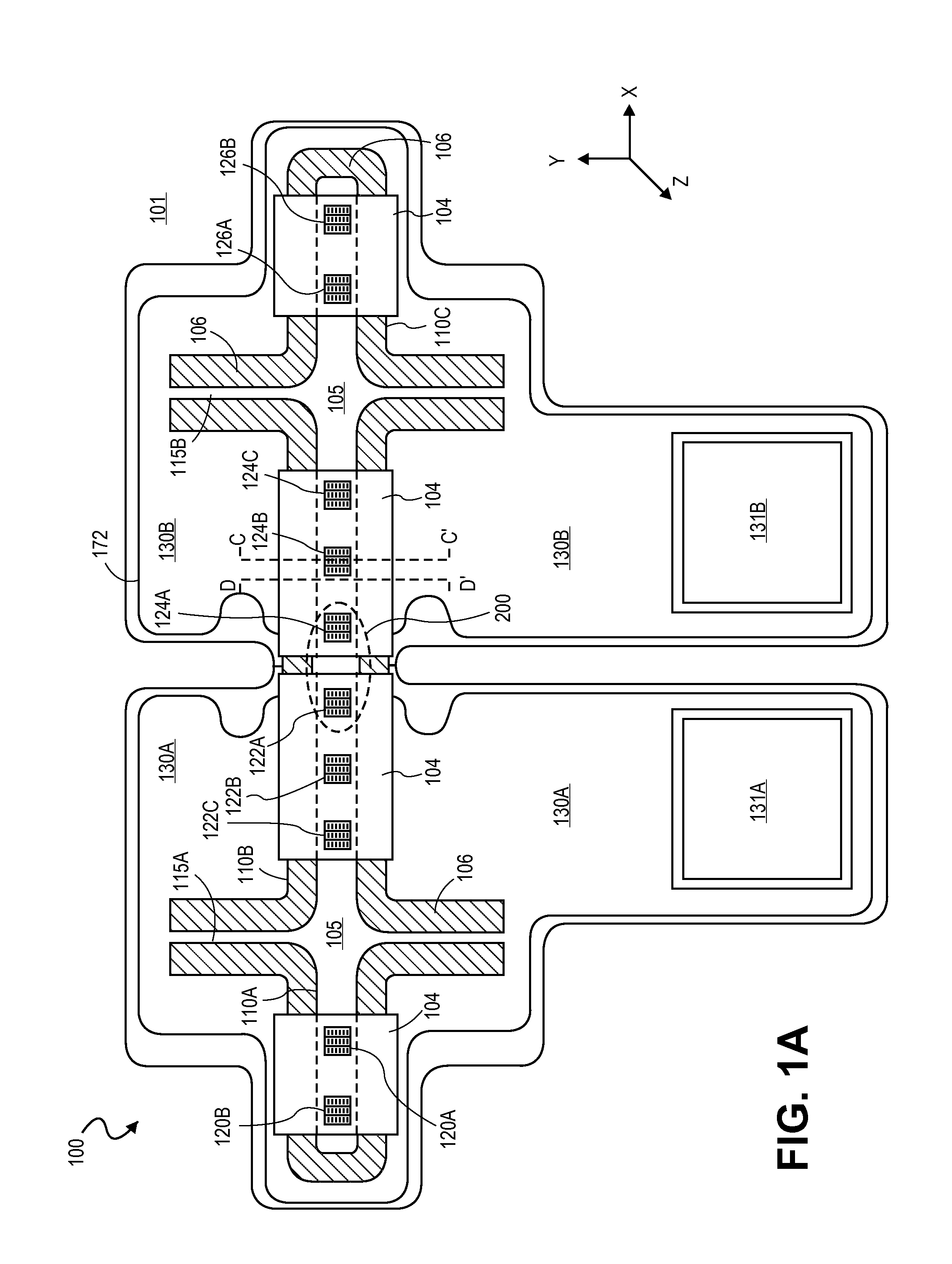
[0009]In embodiments, a resonator has a bulk substrate thickness substantially equal to that of the support for increased dimensional mass, increased out-of-plane rigidity, and increased conductive cross-section at anchor points. In certain such embodiments, separate crystalline layers of a silicon-on-insulator (SOI) substrate are electrically connected with conductive vias through the insulator layer to form conductive anchors through an entire thickness of the support substrate.
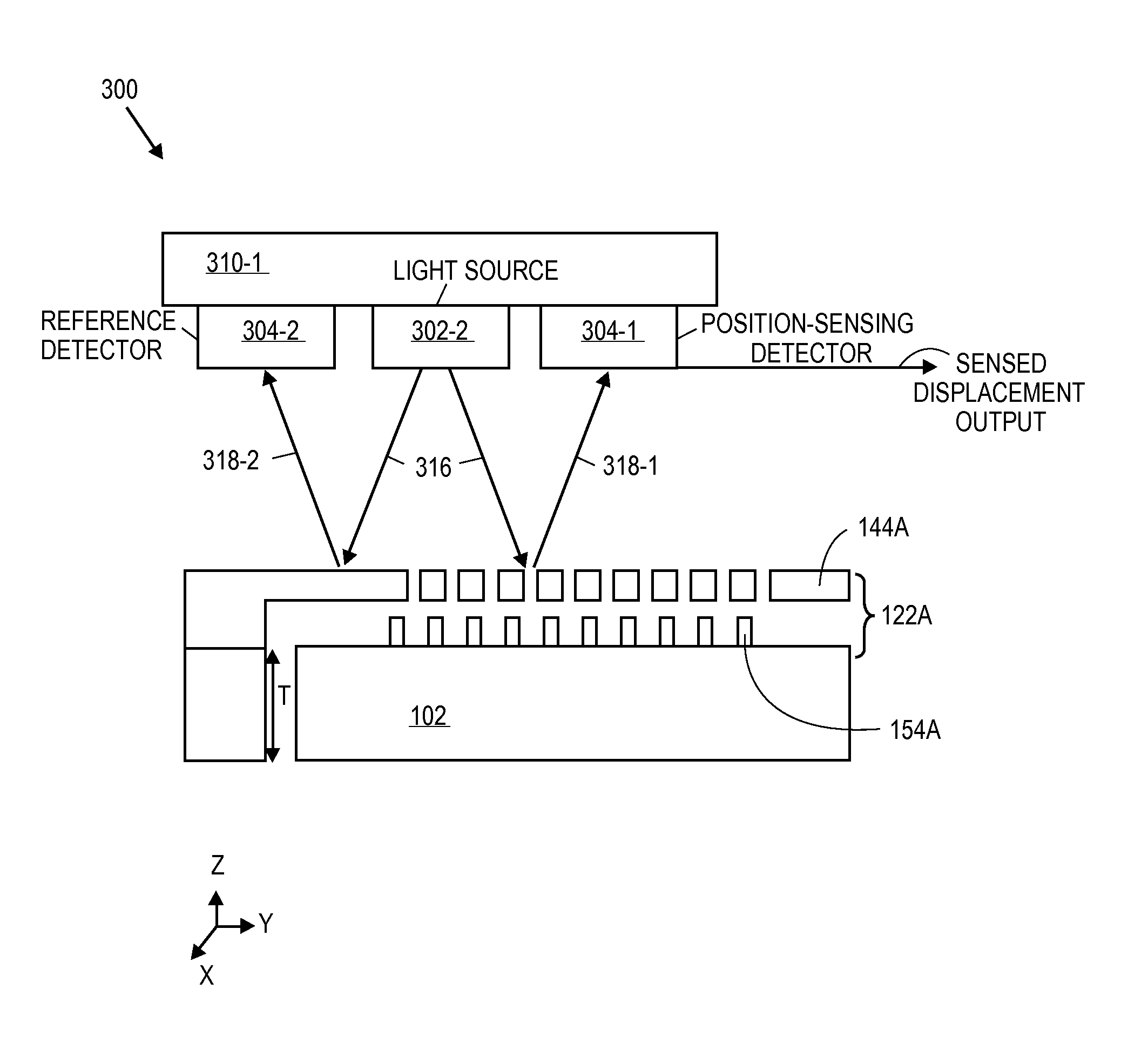
[0010]In embodiments, methods of sensing a magnetic field include placing embodiments of the MEMS magnetometer described herein in a magnetic field and measuring the amplitude, or another displacement characteristic of resonance induced in the resonator, in response to the Lorentz effect of alternating current tuned to a resonant frequency of the resonator passing through the resonator. In certain such embodiments, light sources interrogate the multi-level gratings with a wavelength of light that is greater than grating feature dimensions (e.g., spaces or line elements) and intensity modulation of zeroth orders reflected or transmitted through the grating are sensed with a photosensitive device. Intensity variations are output for determination of magnetic field strength.

Problems solved by technology

However, the conventional sensing techniques suffer from cross-talk and inherent sensitivity and other limitations.
Both capacitive and piezoelectric techniques may also lack dynamic range such that many separate devices are required to conduct field measurements within different magnetic environments or where field strength varies widely and / or rapidly over time.

Method used


Image

  • Optically transduced MEMS magnetometer
  • Optically transduced MEMS magnetometer
  • Optically transduced MEMS magnetometer

Examples


Embodiment Construction

[0019]In the following description of optically transduced MEMS magnetometers, numerous details are set forth, however, it will be apparent to one skilled in the art, that the present invention may be practiced without these specific details. In some instances, well-known methods and devices are shown in block diagram form, rather than in detail, to avoid obscuring the present invention. Reference throughout this specification to “an embodiment” means that a particular feature, structure, function, or characteristic described in connection with the embodiment is included in at least one embodiment of the invention. Thus, the appearances of the phrase “in an embodiment” in various places throughout this specification are not necessarily referring to the same embodiment of the invention. Furthermore, the particular features, structures, functions, or characteristics may be combined in any suitable manner in one or more embodiments. For example, a first embodiment may be combined with ...


PUM


Abstract

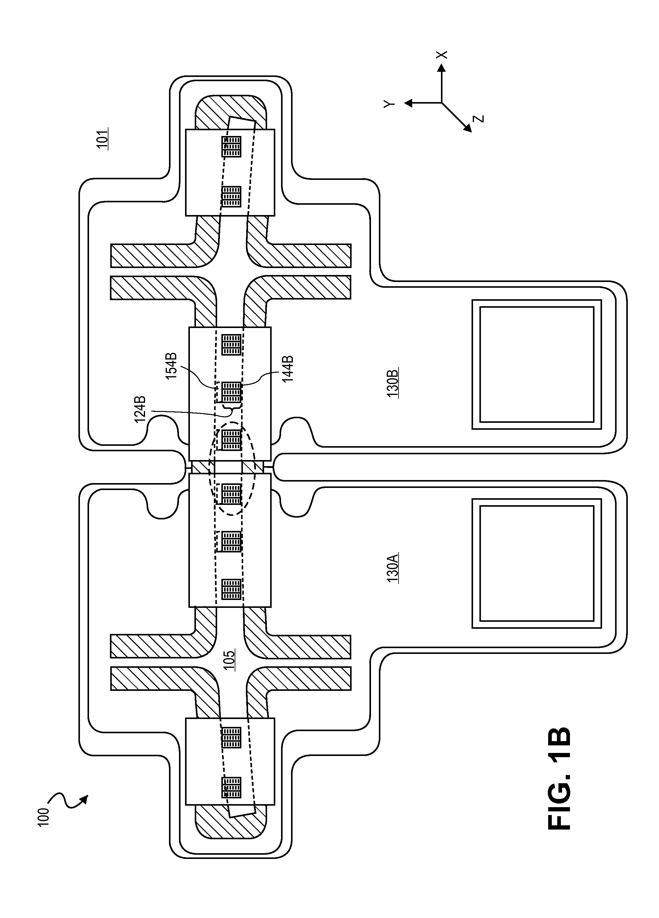
MEMS magnetometers with optically transduced resonator displacement are described herein. Improved sensitivity, crosstalk reduction, and extended dynamic range may be achieved with devices including a deflectable resonator suspended from the support, a first grating extending from the support and disposed over the resonator, a pair of drive electrodes to drive an alternating current through the resonator, and a second grating in the resonator overlapping the first grating to form a multi-layer grating having apertures that vary dimensionally in response to deflection occurring as the resonator mechanically resonates in a plane parallel to the first grating in the presence of a magnetic field as a function of the Lorentz force resulting from the alternating current. A plurality of such multi-layer gratings may be disposed across a length of the resonator to provide greater dynamic range and/or accommodate fabrication tolerances.

Description

GOVERNMENT INTERESTS[0001]Embodiments of the invention were developed under Contract No. DE-AC04-94AL85000 between Sandia Corporation and the U.S. Department of Energy. The United States Government has certain rights in this invention.RELATED APPLICATIONS[0002]This application is related to U.S. patent application Ser. No. 13 / 325,683, entitled OPTICALLY TRANSDUCED MEMS GYRO DEVICE, to Nielson, et al., filed even date herewith, the entirety of which is incorporated herein by reference for all purposes.TECHNICAL FIELD[0003]The present invention generally relates to Micro Electro-Mechanical System (MEMS) sensors, and more particularly to Lorentz force magnetometers.BACKGROUND[0004]Many conventional MEMS force and inertial sensors, such as accelerometers, magnetometers, and magnetometers, etc. include a pair of drive electrodes to which an alternating current (AC) is applied to induce a mechanical resonance in a suspended member.[0005]In Lorentz force magnetometers, the alternating curr...

Claims


Application Information

Patent Timeline
Patent Type & Authority Patents(United States)
IPC IPC(8): G01R33/02
CPCG01R33/0286G01R33/032G01R33/02
Inventor NIELSON, GREGORY N.LANGLOIS, ERIC
Owner NAT TECH & ENG SOLUTIONS OF SANDIA LLC
Why Eureka
Try Eureka