Injection device

a technology of injection device and injection chamber, which is applied in the direction of valve operating means/releasing devices, machines/engines, mechanical apparatus, etc., can solve the problems of chemical or physical damage to the medium to be injected and the actuator, high cost, and complex injection device, etc., to achieve more homogeneous and improved spray, easy and inexpensive manufacturing, and simple geometry and configuration

Inactive Publication Date: 2014-03-25
ROBERT BOSCH GMBH
View PDF17 Cites 0 Cited by
  • Summary
  • Abstract
  • Description
  • Claims
  • Application Information

AI Technical Summary

Benefits of technology

[0006]The injection device according to the present invention having the features described herein has, by contrast, the advantage that it both has a simpler geometry and configuration, and accordingly is easy and inexpensive to manufacture, and produces a more homogeneous and improved spray. In accordance with the exemplary embodiments and / or exemplary methods of the present invention, that is achieved by virtue of the fact that the injection device has a pulse-transmitting device which is arranged between the valve arrangement and the actuator device and which separates the valve arrangement, which is in contact with the medium, from the actuator device in a fluid-tight manner. The simple construction of the actuator device, which is not arranged in the medium, prevents potential interactions between medium and actuator and enables optimized pulse transmission to be achieved by the pulse-transmitting device, which results in a more homogeneous injection spray and consequently in improved combustion with lower fuel consumption and reduced emissions.

Problems solved by technology

Such injection devices are, however, very complex and, in particular, expensive since to prepare the spray either high system pressures are generated in order to convert hydraulic pressure energy into kinetic energy or, in alternative methods, spray production is accomplished using high-frequency shock waves.
The contact of the actuators used to generate the shock waves with the medium that is to be injected may lead to interactions between the medium and the actuators, which may result in chemical or physical damage both to the medium to be injected and to the actuators.
Furthermore, the quality of the spray is unsatisfactory as regards droplet size distribution and velocity of the spray front both in the case of actuators for spark discharge and in the case of piezo actuators.
For that reason, the solutions mentioned have only inadequate suitability for use in, for example, modern diesel engines.

Method used


Image

  • Injection device
  • Injection device
  • Injection device

Examples


Embodiment Construction

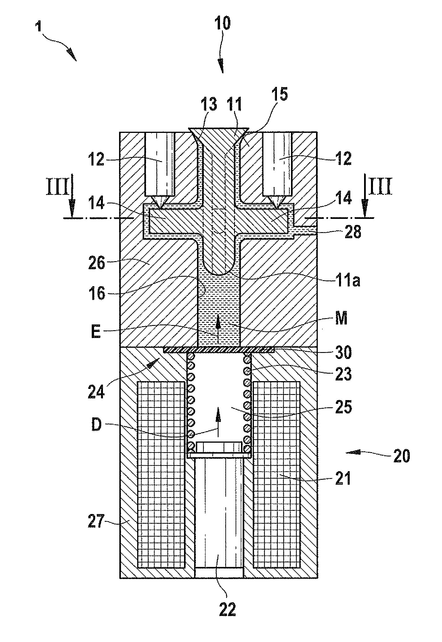
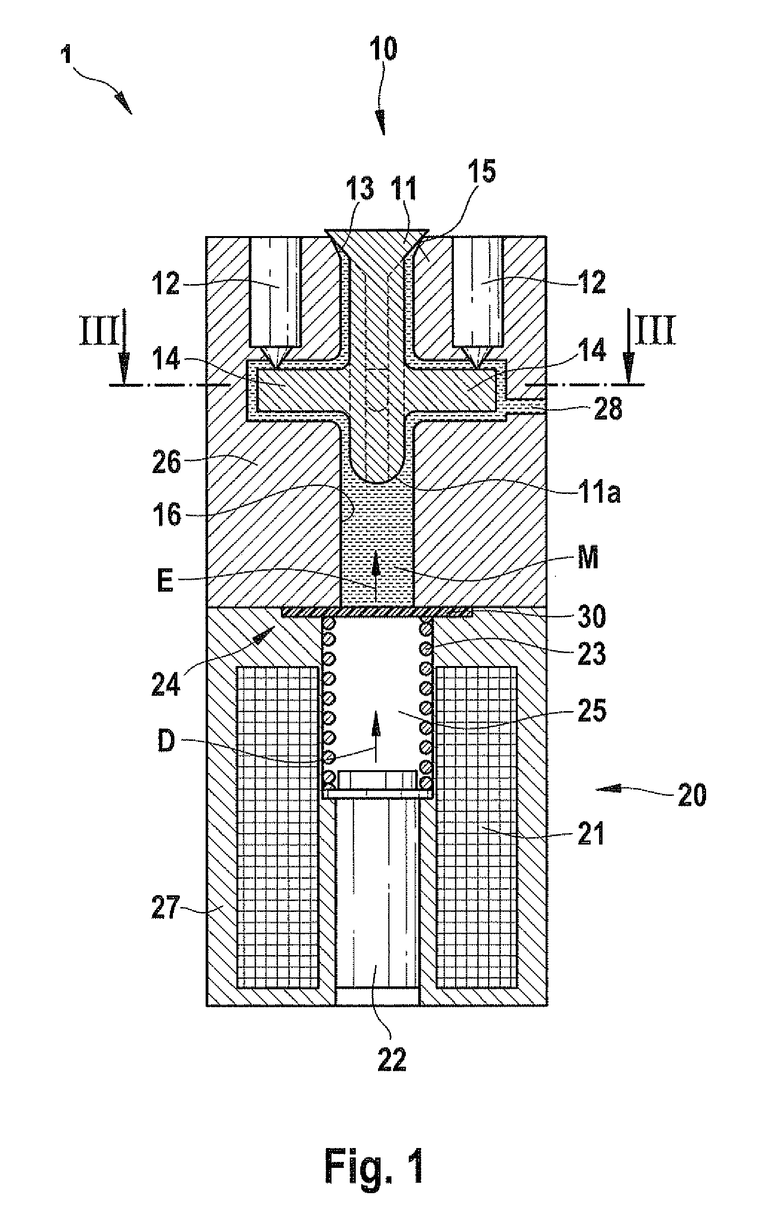
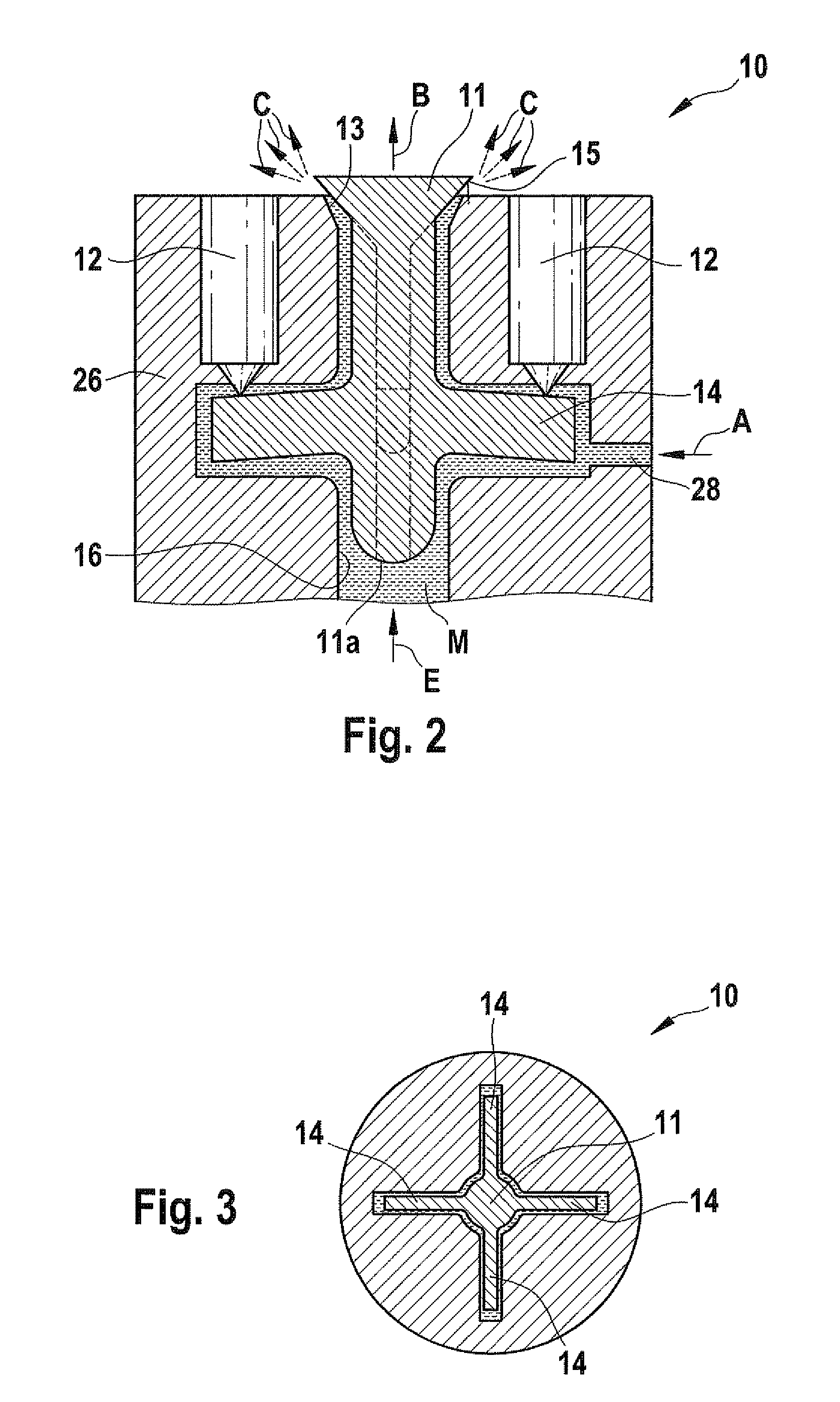
[0024]An injection device 1 of the present invention in accordance with a first exemplary embodiment is described in detail below with reference to FIGS. 1 to 3.

[0025]FIG. 1 is a schematic sectional illustration of injection device 1 in the closed state, including in a first housing part 26 a valve arrangement 10 with a sealing valve member 11 and a bearing device 12 with four bearing elements. As may be seen from FIG. 1, valve arrangement 10 is arranged in a metering chamber 16 in medium M to be injected which is supplied through a feed duct 28.

[0026]Valve member 11 is arranged on a valve seat 13 and has a conical surface 15. The valve member further includes a rounded rear end 11a and a plurality of arms 14 of which only two are visible in this sectional illustration.

[0027]As may be seen from FIG. 3, which is a sectional illustration of valve arrangement 10 along the line III-III of FIG. 1, in this exemplary embodiment valve member 11 may have four arms 14 arranged circumferential...


PUM


Abstract

An injection device for injecting a medium, including a valve arrangement with a valve member forming a seal at a valve seat, wherein the valve arrangement is arranged in the medium to be injected, an actuator device with an actuator, a plunger and a return element, and a pulse-transmitting device which is arranged between the valve arrangement and the actuator device, which separates the valve arrangement from the actuator device in a fluid-tight manner and which transmits a pulse generated by the actuator device to the medium to be injected in order in that manner to open the valve arrangement and inject medium.

Description

RELATED APPLICATION INFORMATION[0001]The present application claims priority to and the benefit of German patent application no. 10 2008 042 850.7, which was filed in Germany on Oct. 15, 2008, the disclosure of which is incorporated herein by reference.FIELD OF THE INVENTION[0002]The present invention relates to an injection device having a valve arrangement, an actuator device, and a pulse-transmitting device which separates the valve arrangement from the actuator device in a fluid-tight manner and which transmits a pulse generated by the actuator device to the medium to be injected. The present invention further relates to a method for injecting a medium by an injection device, wherein a pulse generated by the actuator device is transmitted via the pulse-transmitting device to the medium and then to the valve arrangement.BACKGROUND INFORMATION[0003]There are injection devices from the related art in various embodiments. What is particularly important in this area is the production...

Claims


Application Information

Patent Timeline
Patent Type & Authority Patents(United States)
IPC IPC(8): B05B1/30
CPCF02M69/041F02M63/06
Inventor OHLHAFER, OLAFGIEZENDANNER-THOBEN, ROBERT
Owner ROBERT BOSCH GMBH
Why Eureka
Try Eureka