Centrifugal separator separating disc interspace configurations

a technology of interspace configuration and centrifugal separator, which is applied in the direction of centrifuges, rotary centrifuges, etc., can solve the problems of difficult to produce irregular shapes such as protrusions in pressure-turned disks, and difficulty in achieving a sufficient surface smoothness, and achieves low cost

Inactive Publication Date: 2014-03-25
ALFA LAVAL CORP AB
View PDF22 Cites 22 Cited by
  • Summary
  • Abstract
  • Description
  • Claims
  • Application Information

AI Technical Summary

Benefits of technology

[0009]One object of the present invention is to provide a separating disk which may be manufactured in an easy manner and to low costs. At the same time it is aimed at a separating disk that permits a uniform and tight abutment between the contact zones of the separating disks in a disk package.
[0011]Such a separating disk can be readily manufactured since the pressing can be made in a press tool in a very short time-period. The subsequent work of attaching or shaping distance members disappears according to the invention, since it is possible to provide shape and distance creating means in the form of protrusions in one and the same pressing operation. The cost of manufacturing for each separating disk ought to be significantly lower than for the previously utilized pressure turning method. Furthermore, through such a pressing a deformation hardening of separating disks of a metal material is achieved so that a high strength, permitting use of thin blanks, is obtained.
[0012]According to an embodiment of the present invention, each contact zone has a continuously convex shape seen in a cross-section. Such a shape can advantageously be provided in a press tool. Such a shape also enables a small contact area to an adjacent separating disk in the disk package, i.e. the contact area approaches zero. The contact zone can be defined as forming a point or line abutment, or substantially a point or line abutment, against the inner surface or the outer surface of the adjacent separating disk. Such a minimized contact area results in good hygienic properties of the disk package since this is easy to clean. The minimized contact area significantly reduces the quantity of particles and microorganisms, such as bacteria, that can be attached in the area of the distance members.

Problems solved by technology

This method of manufacturing has the disadvantage that the manufacturing is expensive and time-consuming.
Another disadvantage of the pressure turning method is that it is difficult to produce irregular shapes such as protrusions in the pressure turned disk.
A further disadvantage of the pressure turning method is the difficulty to achieve a sufficient surface smoothness without subsequent treatment of the surface.
A poor surface smoothness can lead to deteriorated hygienic properties.
One problem with the solution disclosed in U.S. Pat. No. 2,028,955 is that the disk package during compression is relatively rigid since the relatively hard projections and depressions lies after each other in a radial direction in the disk package, and in addition opposite to each other.
A further disadvantage is that the distance members, and especially the depressions, may have a negative influence to the flow in the interspace in the separating disks.

Method used


Image

  • Centrifugal separator separating disc interspace configurations
  • Centrifugal separator separating disc interspace configurations
  • Centrifugal separator separating disc interspace configurations

Examples


first embodiment

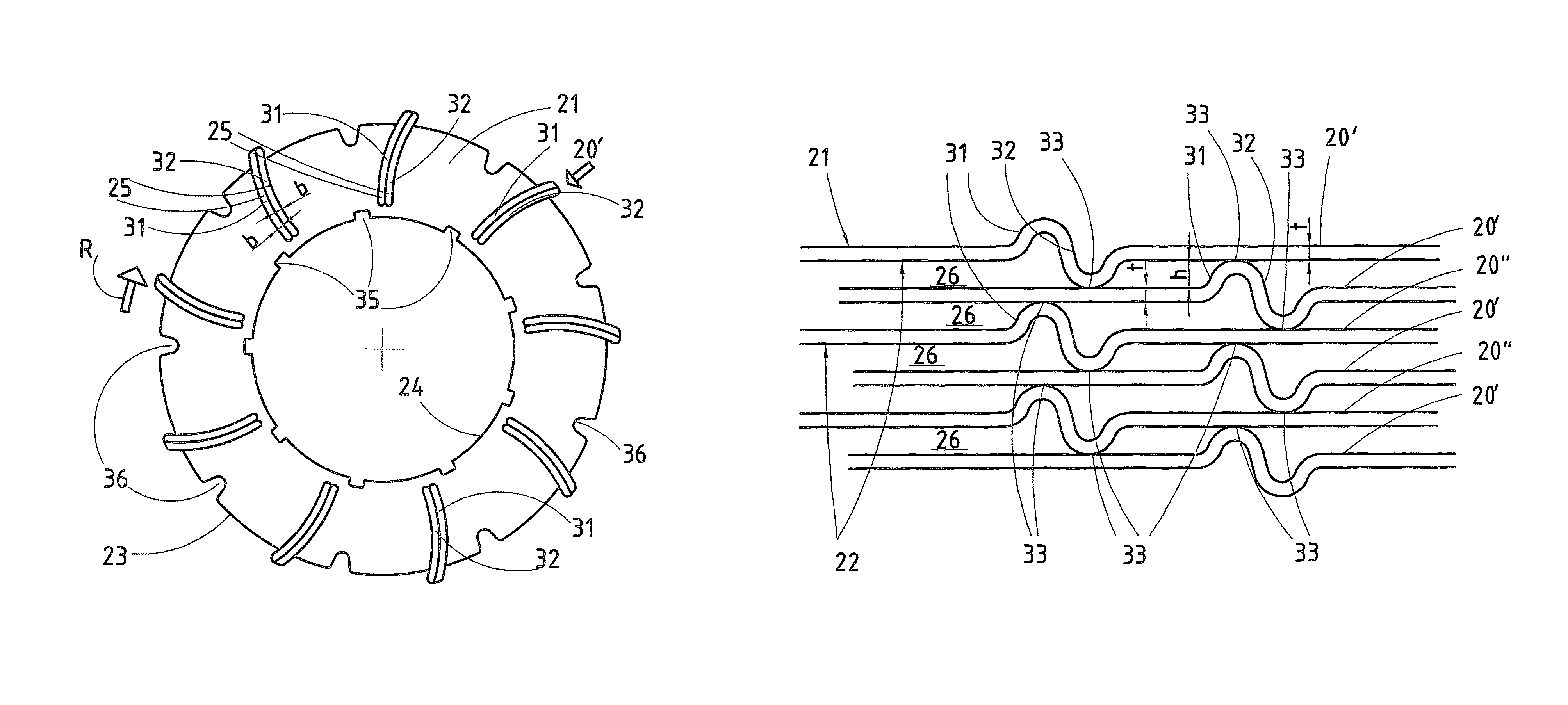
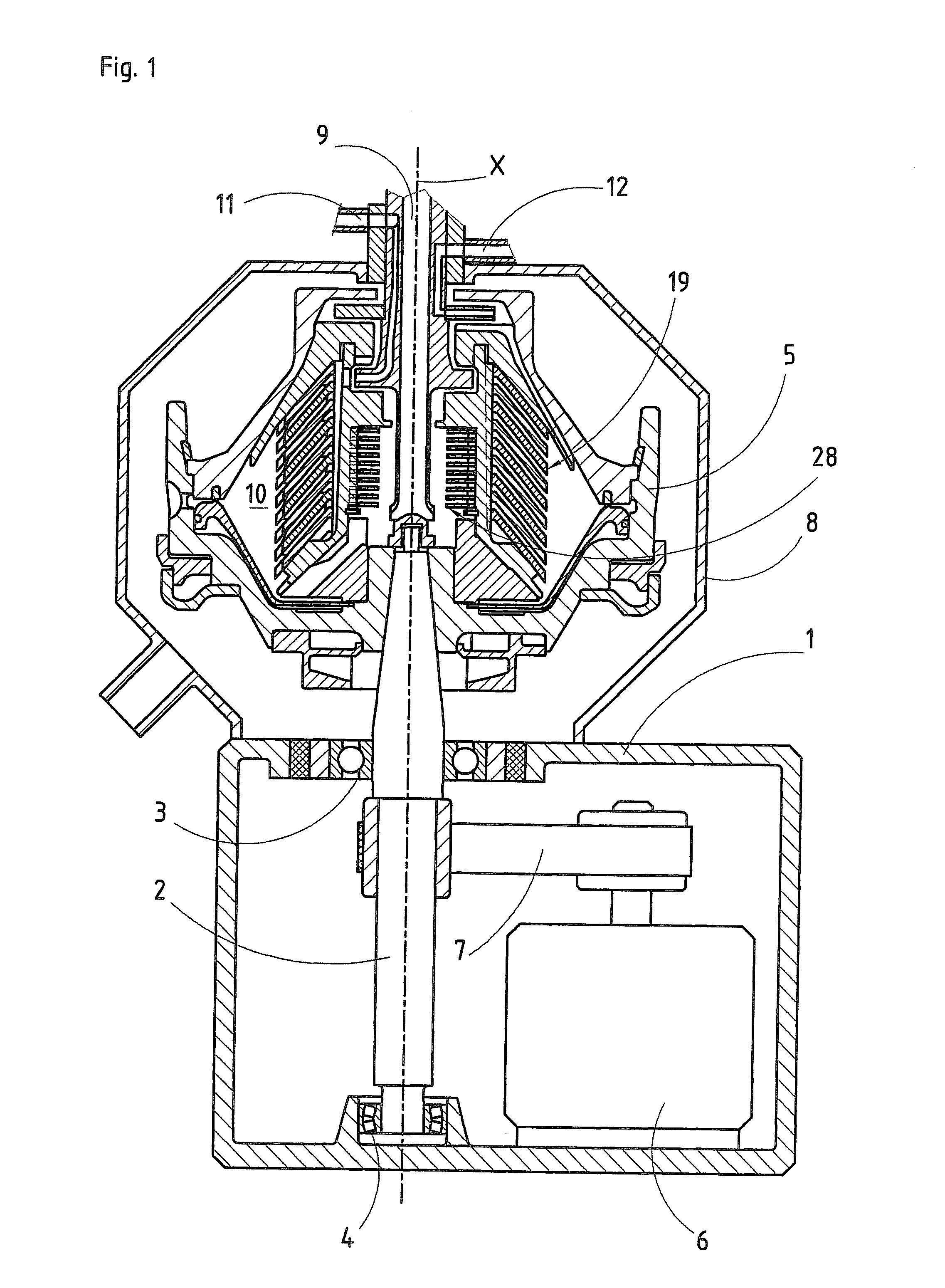
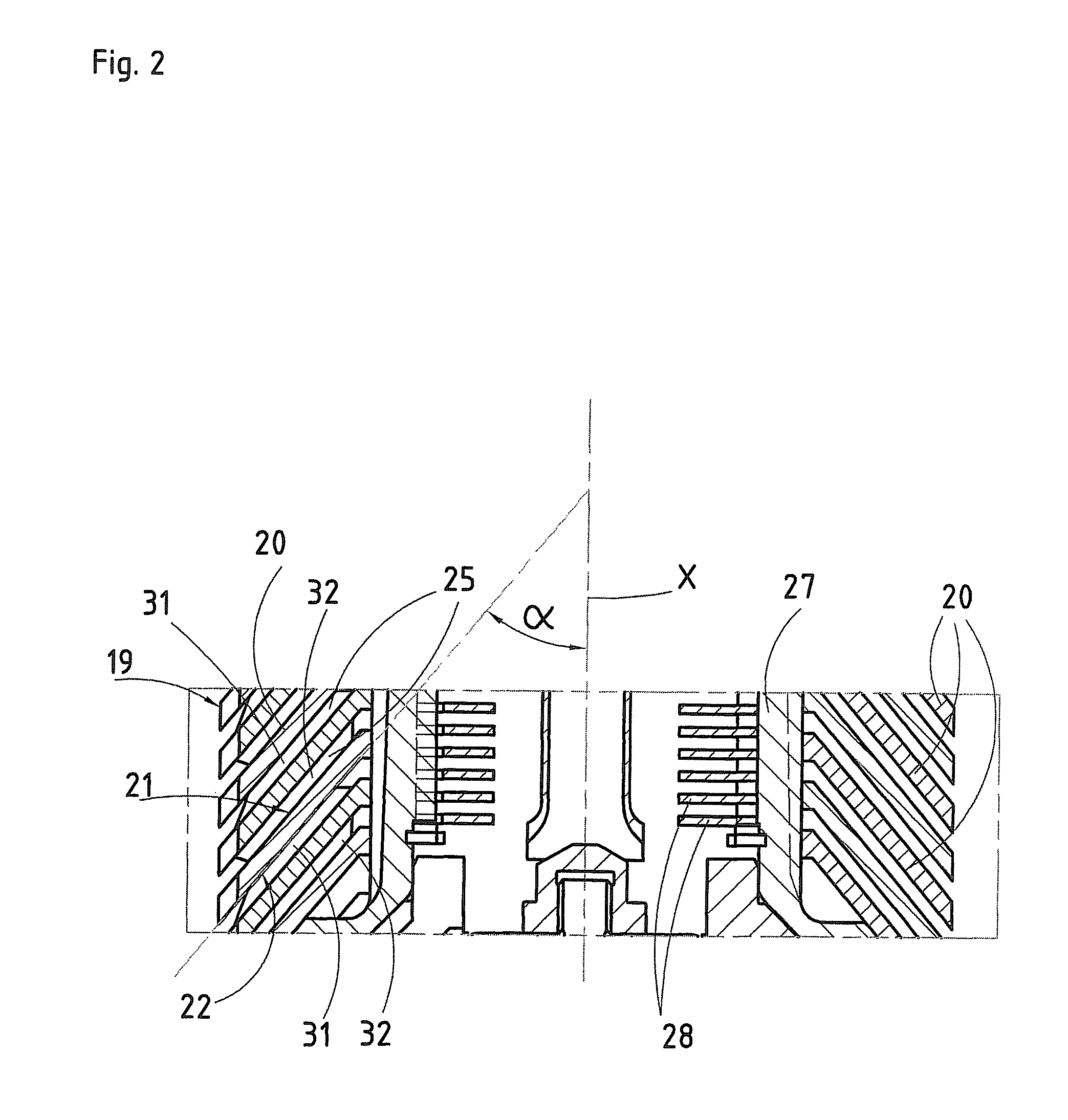
[0040]In the separation space 10, there is a disk package 19 which rotates with the centrifuge rotor 5. The disk package 19 comprises or is assembled of a plurality of separating disks 20 which are piled onto each other in the disk package 19, see FIG. 2. A separating disk 20 is disclosed more closely in FIGS. 3 and 4. Each separating disk 20 extends around the axis x of rotation and rotates around the axis x of rotation in a direction R of rotation. Each separating disk 20 extends along a rotary symmetric, or virtually rotary symmetric, surface y, see FIG. 5, which tapers along the axis x of rotation, and has a tapering shape along the axis x of rotation with an outer surface 21, which is convex, and an inner surface 22, which is concave. The tapering shape of the separating disks 20 may also be conical or substantially conical, but it is also possible to let the tapering shape of the separating disks 20 have a generatrix which is curved inwardly or outwardly. The separating disks...

second embodiment

[0057]According to the disk package 19, see FIG. 6, also each second separating disk 20″ may comprise a number of distance members in the form of pressed first and second protrusions 31 and 32, i.e. all separating disks 20 are provided with first and second protrusions 31 and 32. In this case, the separating disks 20 mat be polar-positioned in such a way that a first protrusions 31 of the first separating disks 20′ are displaced in relation to the first protrusions 31 of the second separating disks 20″ in the disk package 19 seen in the direction of the axis x of rotation.

[0058]FIG. 7 discloses a third embodiment where the distance members 25, i.e. the protrusions 31, 32, have such an extension in the peripheral direction that each first protrusion 31 and second protrusion 32 adjoins a portion lacking protrusions and extending along the tapering rotary symmetric surface y. The contact zones 33 of the first protrusions 31 are provided at a significant distance from the contact zones ...

sixth embodiment

[0061]It is to be understood that the polar-positioning of the separating disks 20 may be varied in many different ways in addition to the ways disclosed in FIGS. 5 and 6. FIG. 10 discloses a sixth embodiment where two first separating disks 20′ are provided beside each other and each such pair of first separating disks 20′ are separated by a second separating disk 20″. The first protrusion 31 of a first separating disk 20′ in such a pair lies opposite to the second protrusion 32 of the second first separating disk 20′ in this pair, and opposite the first protrusions 31 of corresponding disks 20′ in the remaining pairs.

[0062]FIG. 11 discloses a seventh embodiment which is similar to the sixth embodiment, but differs from the latter since one of the first separating disks 20′ has been modified and is a third separating disk 20′″ which comprises a first protrusion 31 but no second protrusion 32. The first protrusion 31 of the third separating disk in each pair lies opposite to the sec...


PUM

PropertyMeasurementUnit
angleaaaaaaaaaa
distanceaaaaaaaaaa
timeaaaaaaaaaa

Abstract

A separating disk for a disk package of a centrifuge rotor of a centrifugal separator has a tapering shape and extends around an axis of rotation and along a tapering rotary symmetric surface along the axis of rotation. There is an interspace between the separating disk and an adjacent separating disk. The separating disc has first protrusions extending outwardly from the tapering rotary symmetric surface and second protrusions extending inwardly from the tapering rotary symmetric surface. Each of the first and second protrusion are after each other in a peripheral direction and define a contact zone adapted to abut an adjacent separating disk in the disk package. The contact zones of the first protrusions are displaced in relation to the contact zones of the second protrusions seen in a normal direction with regard to the outer surface. Each contact zone has a continuously convex cross sectional shape.

Description

FIELD OF THE INVENTION[0001]The present invention refers to a separating disk adapted to be included in a disk package of a centrifuge rotor of a centrifugal separator. The invention also refers to a disk package.BACKGROUND OF THE INVENTION[0002]Today separating disks for disk packages in centrifuge rotors are normally manufactured through pressure turning of plane disks to a desired tapering shape, for instance a conical shape. This method of manufacturing has the disadvantage that the manufacturing is expensive and time-consuming. Each separating disk has to be pressure turned individually in a pressure lathe. Another disadvantage of the pressure turning method is that it is difficult to produce irregular shapes such as protrusions in the pressure turned disk. A further disadvantage of the pressure turning method is the difficulty to achieve a sufficient surface smoothness without subsequent treatment of the surface. A poor surface smoothness can lead to deteriorated hygienic prop...

Claims


Application Information

Patent Timeline
Patent Type & Authority Patents(United States)
IPC IPC(8): B04B7/14B04B1/08
CPCB21D26/021B04B7/14B04B1/08B21D22/22B21D22/20B04B1/04B04B5/12B21D22/00
Inventor RUDMAN, LARS JOHANOLSSON, SVEN OLOVKLINTENSTEDT, KJELL
Owner ALFA LAVAL CORP AB
Why Eureka
Try Eureka