Smokeless coffee roaster

a roaster and coffee technology, applied in the field of roasting coffee, to achieve the effect of high heat in the incineration tub

Active Publication Date: 2014-03-25
LORING SMART ROAST
View PDF16 Cites 4 Cited by
  • Summary
  • Abstract
  • Description
  • Claims
  • Application Information

AI Technical Summary

Problems solved by technology

Although the patented coffee bean roasting system was mostly smokeless, at the end of the roast there was smoke in the roaster and the beans cooling in ambient air made more smoke.

Method used


Image

  • Smokeless coffee roaster
  • Smokeless coffee roaster
  • Smokeless coffee roaster

Examples


Embodiment Construction

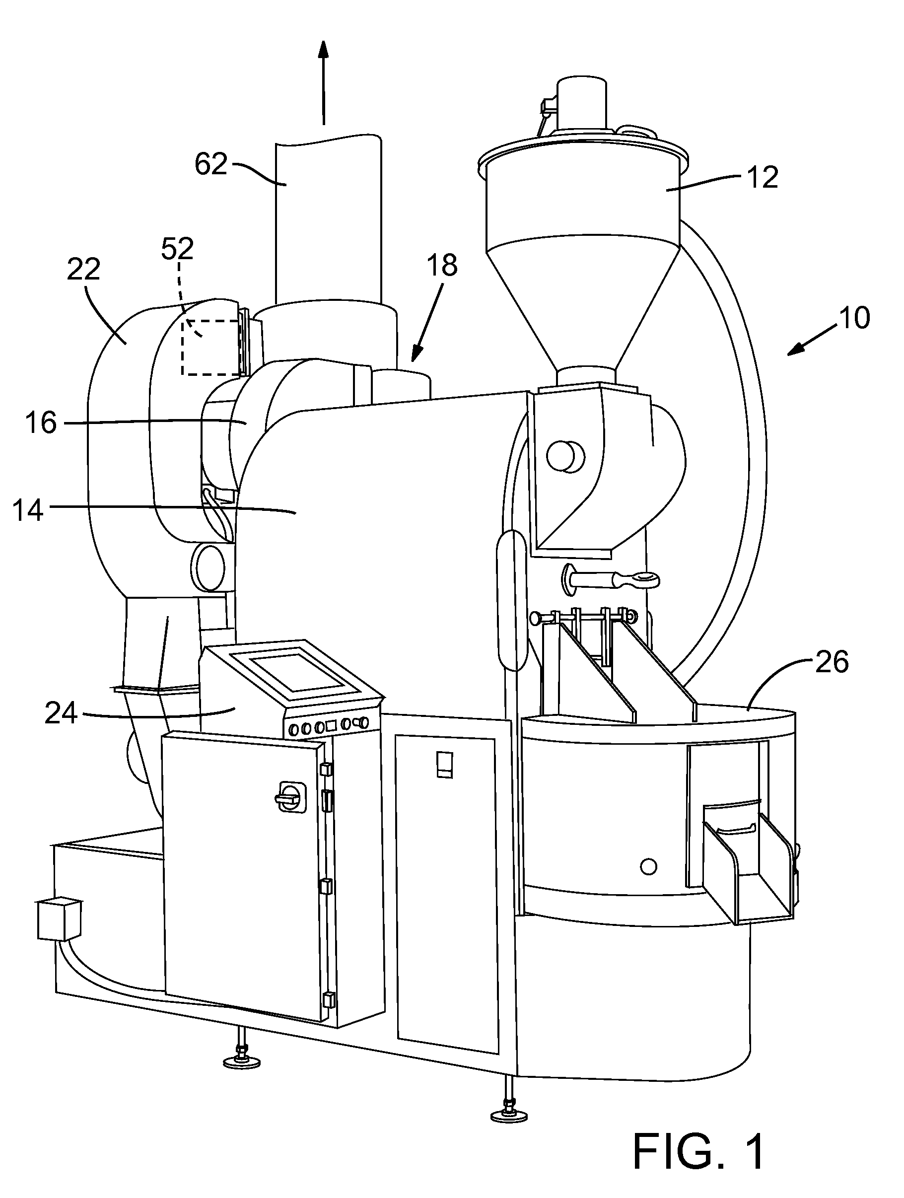
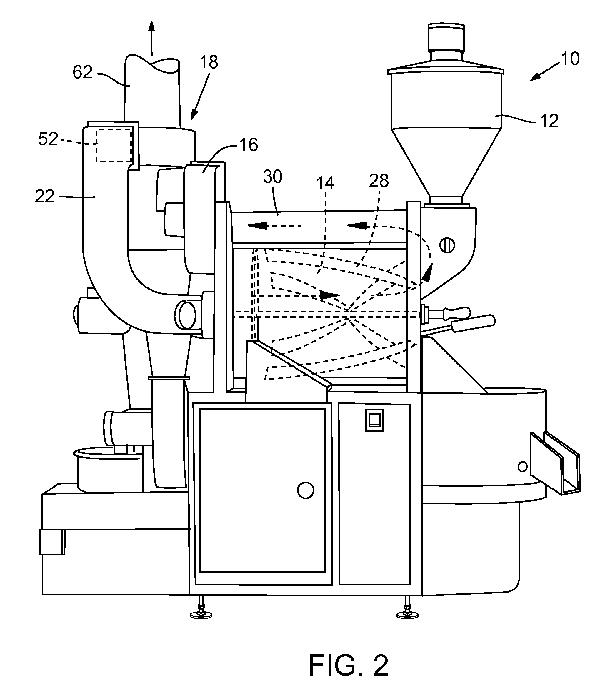
[0016]FIG. 1 shows a coffee bean roaster 10 according to the invention, generally as described in U.S. Pat. No. 5,944,512. The operation of the machine, for a generically described heating application, is described in the patent and that description is incorporated herein by reference.

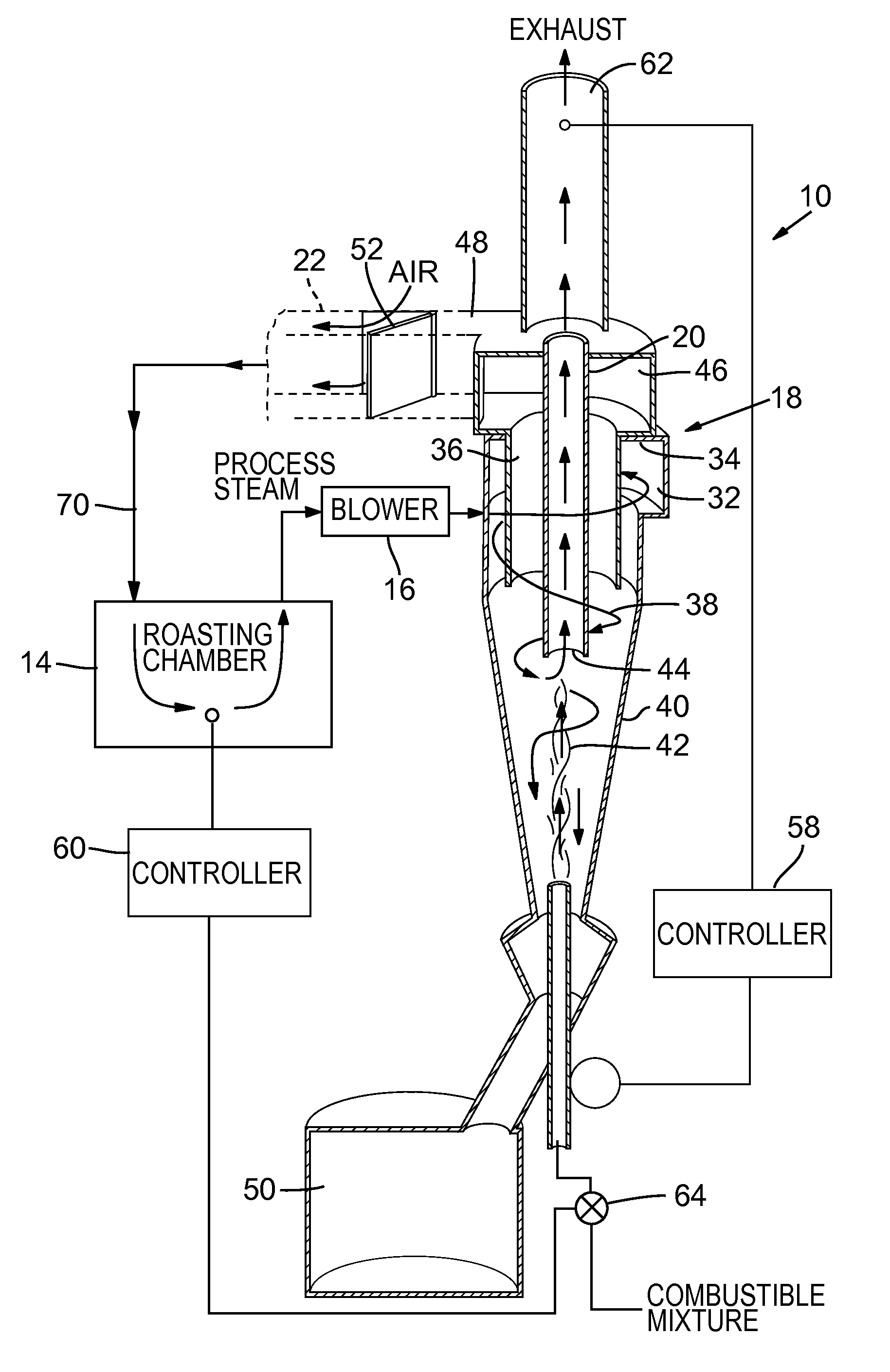
[0017]The machine 10 has a coffee bean hopper 12, a bean roasting chamber 14, a circulating fan or blower 16 delivering a process stream of gases from the roasting chamber to a cyclone separator 18, only an upper portion of which is seen in FIG. 1, an incineration tube and chamber 20 for exhaust from the cyclone separator, a duct 22 leading from the exit of the cyclone separator 18 back to the roasting chamber 14, controls 24 and a bean cooling tray 26 for receiving roasted coffee beans from the roasting chamber 14. The controls 24 include a computer preferably with a touch screen monitor for user input and system monitoring, the programming in the computer operating the system in accordance with input...


PUM


Abstract

A coffee bean roasting machine of the type having a cyclone separator heating chamber and a coffee bean roasting chamber in a recirculating process stream driven by a recirculation fan is operated to air cool the roasted coffee beans in the roasting chamber, to a temperature beneath which the beans give off smoke, while at the same time incinerating smoke removed from the roasting chamber. A purge gate in ducting between the cyclone separator and the roasting chamber is opened to allow the flow of ambient air into and through the roasting chamber while blocking flow out of the cyclone separator, so that ambient air is directed through the roasting chamber. The smoke and any airborne particulate material from the roasting chamber are carried into the heating chamber and through the incineration tube, where they are incinerated. Preferably the system and process are operated automatically by a computer and programming.

Description

BACKGROUND OF THE INVENTION[0001]This invention primarily concerns coffee bean roasting, although the invention can be applied to other roasting or heating applications as well.[0002]The invention is directed to improvements on the coffee bean roasting apparatus and method described in U.S. Pat. No. 5,944,512, owned by the same assignee as this invention. U.S. Pat. No. 5,944,512 is hereby incorporated by reference in its entirety.[0003]In the apparatus of U.S. Pat. No. 5,944,512, which was applicable to but not specific to coffee beans, coffee beans or other products were roasted in a chamber connected in a recirculating process stream loop with a cyclone separator which included a heating chamber. The patented machine had a gas flame or other heat source emanating from the bottom of the heating chamber and directed concentrically toward an incineration tube directly above. The process stream was introduced tangentially to the cyclone separator, via a circulating fan or blower withi...

Claims


Application Information

Patent Timeline
Patent Type & Authority Patents(United States)
IPC IPC(8): A23F5/04
CPCA23N12/10A23N12/125A23F5/04A23N12/08A47J37/07A23F5/046A23F5/10A47J42/52
Inventor LUDWIG, MARK, L.
Owner LORING SMART ROAST
Why Eureka
Try Eureka