Fractured texture coordinates

a texture coordinate and coordinate technology, applied in the field of computer generated imagery and computer-aided animation, can solve the problems of limiting the ability of users to create enough variants of models, and affecting the accuracy of computer-generated objects. , to achieve the effect of reducing distortions in computer-generated objects

Inactive Publication Date: 2014-03-25
PIXAR ANIMATION
View PDF7 Cites 8 Cited by
  • Summary
  • Abstract
  • Description
  • Claims
  • Application Information

AI Technical Summary

Benefits of technology

[0022]In a still further embodiment, a non-transitory computer-readable medium stores computer-executable code for reducing distortions in computer-generated objects. The computer-readable medium includes code for receiving information defining a first UV parameterization of an object, the first UV parameterization having a plurality of polygons, code for receiving a 3D representation of the object, the 3D representation having a plurality of polygons that each individually corresponding to at least one polygon of the first UV parameterization, code for resizing each polygon in the plurality of polygons of the first UV parameterization based on the 3D representation of the object, and code for generating information defining a second UV parameterization of the object based on each resized and / or reoriented polygon in the plurality of polygons of the first UV parameterization.

Problems solved by technology

One of the challenges in creating these visually appealing images is the can be the balancing of a desire for a highly-detailed image of a character or other object with the practical issues involved in allocating the resources (both human and computational) required to produce those visually appealing images.
Therefore, one issue with the production process is the time and effort involved when a user undertakes to model the geometric description of an object.
However, it may take several hours to several days for a user to design, create, rig, pose, paint, or otherwise prepare a model that can be used to produce the visually desired look for one task.
This involvement in time and effort can limit that ability of the user to create enough variants of the model for use in different stages of the production process or in a single scene to covey particular element of the story or to provide the desired visual effect.
Additionally, artistic control over the look of a model or its visual effect when placed in a scene may also be lost by some attempts at reducing the time and effect in preparing a model that rely too much on automated procedural creation of models.

Method used


Image

  • Fractured texture coordinates
  • Fractured texture coordinates
  • Fractured texture coordinates

Examples


Embodiment Construction

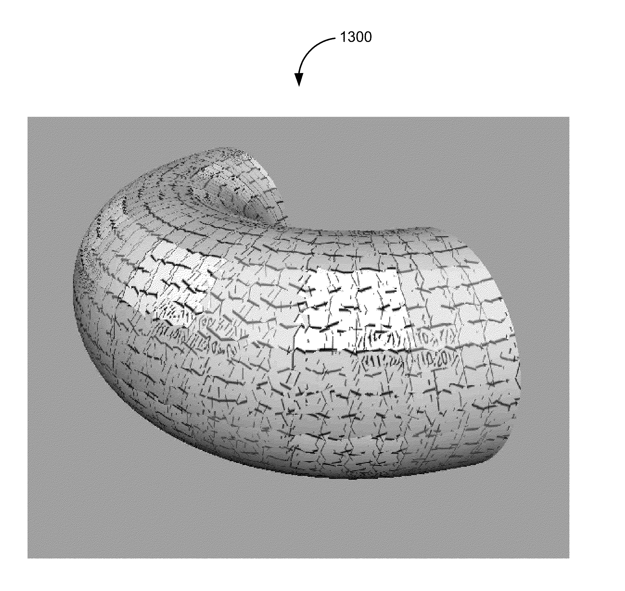
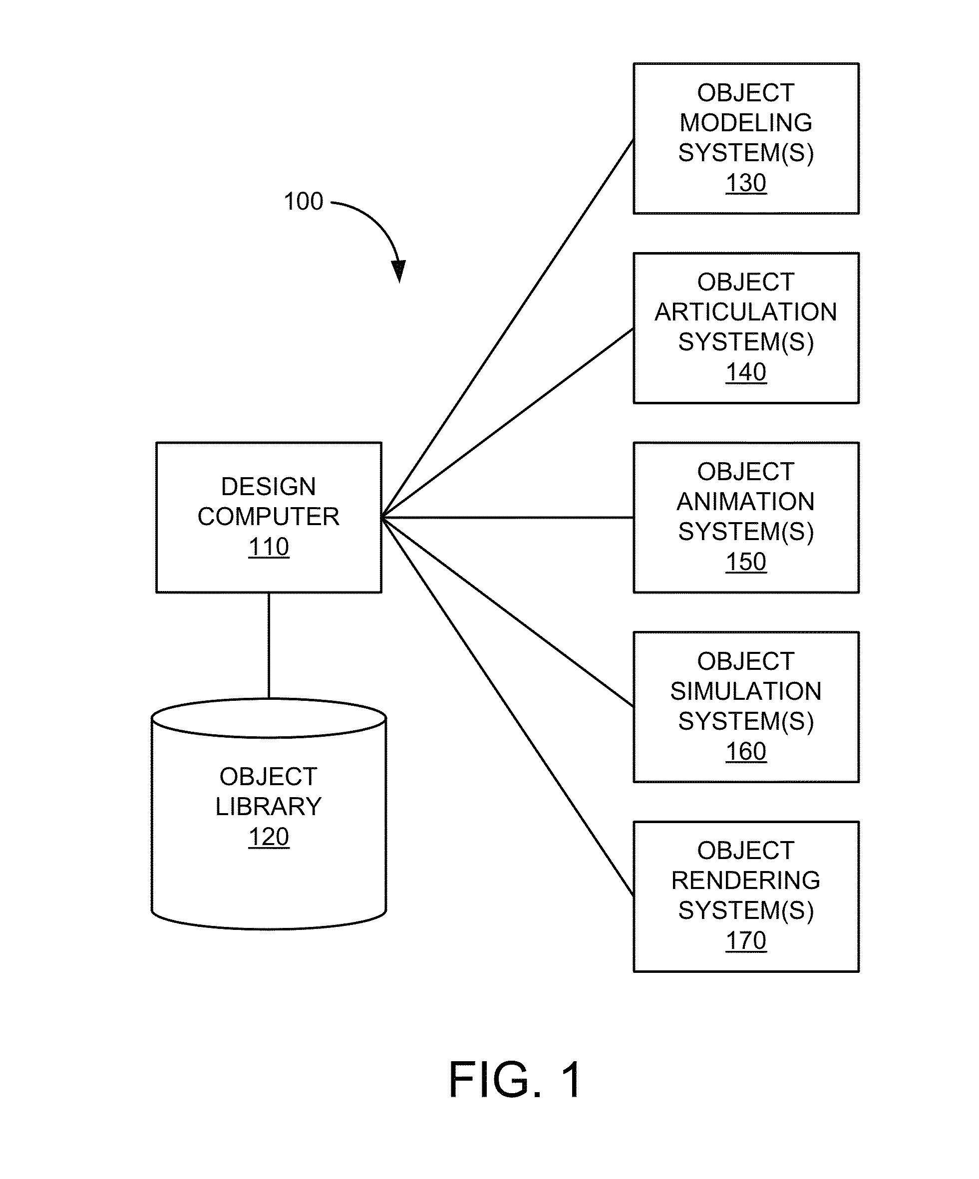
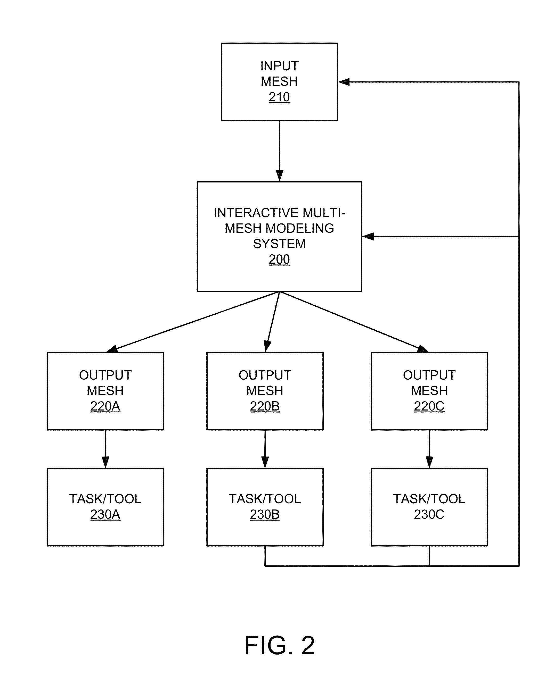
[0040]This disclosure relates to computer-generated imagery (CGI) and computer-aided animation. More specifically, this disclosure relates to interactive modeling system and associated fractured texture coordinates techniques for use in CGI and computer-aided animation.

[0041]In various embodiments, an interactive multi-mesh modeling system may allow users to employ a variety of modeling techniques (e.g., solid modeling or shell / boundary modeling) to interactively create one or more computer-generated representations of objects (e.g., animated characters, static props, and objects whose motions are determined by computer simulations) for a variety of different tasks or tools associated with phases of modeling, layout and animation, and rendering. Some of these different tasks or tools can have requirements for the computer-generated representations of objects on which they operate. These requirements may differ from how some computer-generated representations were originally created ...


PUM


Abstract

In various embodiments, an interactive multi-mesh garment modeling system may allow a user to employ solid modeling techniques to create one or more representations of garment objects whose motions are typically determined by computer simulations. Accordingly, in one aspect, the interactive multi-mesh garment modeling system may automatically generate one or more meshes that satisfy the requirements for computer simulations from a source mesh modeled by a user using solid modeling techniques. For each polygon associated with a UV mapping of one of these meshes, gradients of U and V for the polygon can be determined with respect to a 3D representation of an object that are substantially orthogonal and of uniform magnitude and that approximate the original gradients of U and V for the polygon. In another aspect, each polygon in a plurality of polygons of a 2D parameterization of an object can be reshaped based on individually corresponding polygons in a 3D representation of the object.

Description

CROSS-REFERENCES TO RELATED APPLICATIONS[0001]This Application claims priority to and the benefit of U.S. Provisional Patent Application No. 61 / 248,051, filed Oct. 2, 2009 and entitled “FRACTURED TEXTURE COORDINATES,” which is hereby incorporated by reference for all purposes.[0002]This Application is related to the following commonly owned and co-pending applications:[0003]U.S. patent application Ser. No. 12 / 893,319, filed Sep. 29, 2009 and entitled “Annotation-Based Mesh Modification” which claims priority to U.S. Provisional Patent Application No. 61 / 248,042, filed Oct. 2, 2009 and entitled “Automatic Annotation-Based Mesh Modification,” both of which are hereby incorporated by reference for all purposes.[0004]U.S. patent application Ser. No. 12 / 893,353, filed Sep. 29, 2009 and entitled “Structured Polygonal Mesh Retesselation” which claims priority to U.S. Provisional Patent Application No. 61 / 248,045, filed Oct. 2, 2009 and entitled “Structured Polygonal Mesh Retesselation,” bo...

Claims


Application Information

Patent Timeline
Patent Type & Authority Patents(United States)
IPC IPC(8): G06T15/00
CPCG06T19/20G06T15/04G06T15/00
Inventor BARAFF, DAVIDWAGGONER, CHRISTINE
Owner PIXAR ANIMATION
Why Eureka
Try Eureka