
Active clamp resonance control

a technology of active clamp and resonance control, which is applied in the direction of electric variable regulation, process and machine control, instruments, etc., can solve the problem of inherently difficult limiting stresses of semiconductor switching components of the bridg

Inactive Publication Date: 2014-03-25
TOSHIBA INT
View PDF3 Cites 4 Cited by
  • Summary
  • Abstract
  • Description
  • Claims
  • Application Information

AI Technical Summary

Benefits of technology

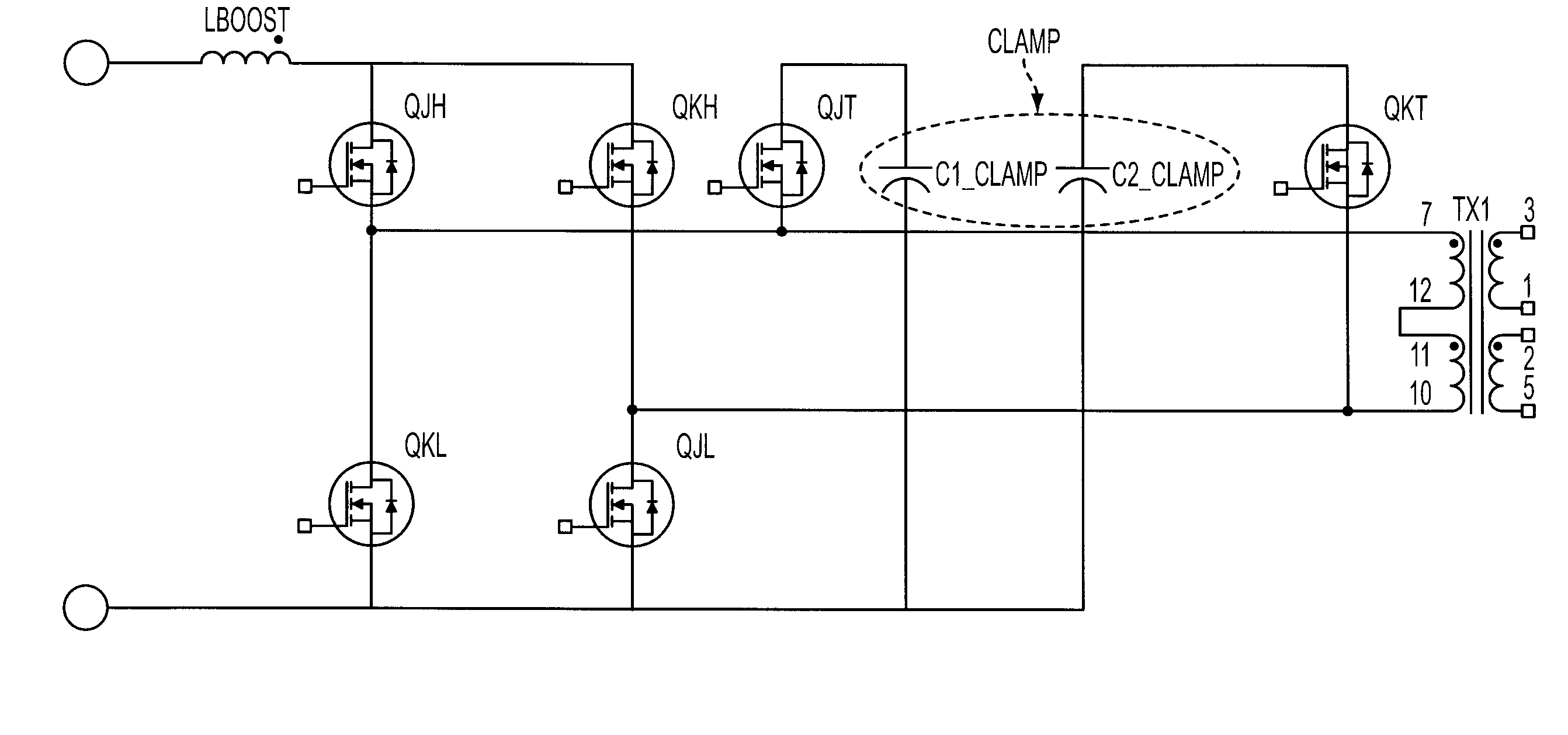
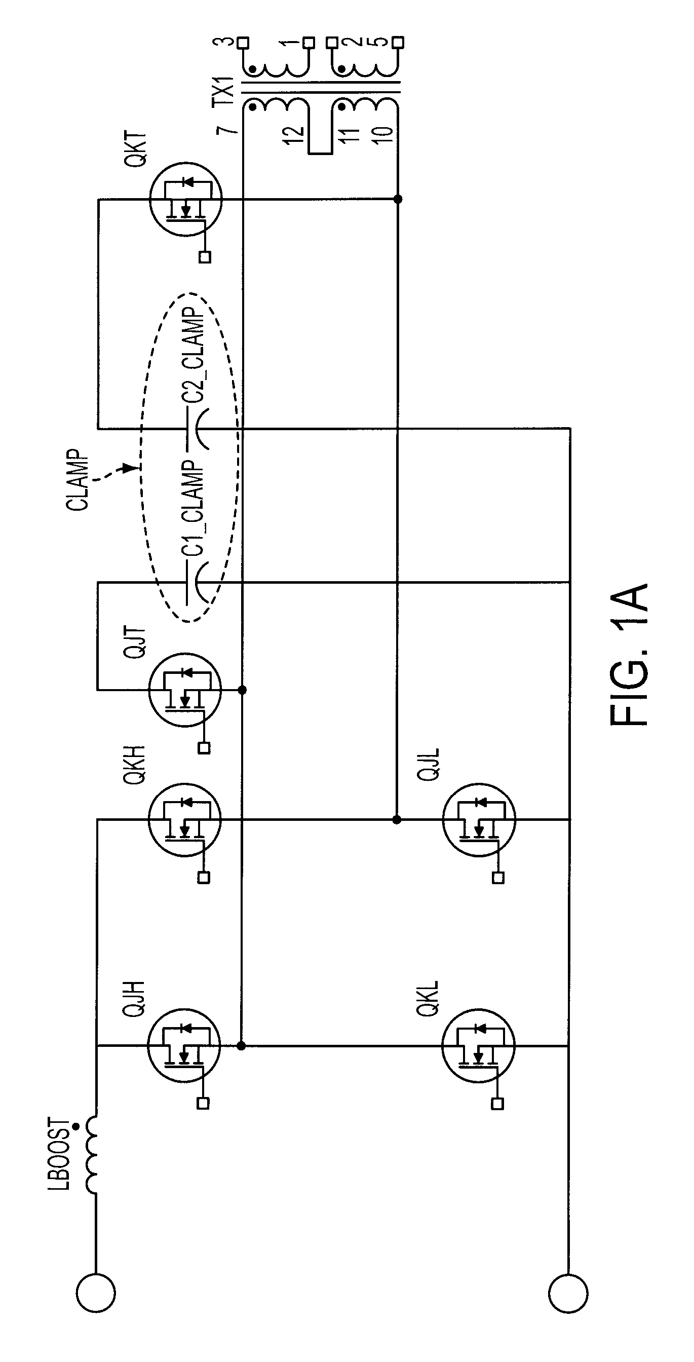
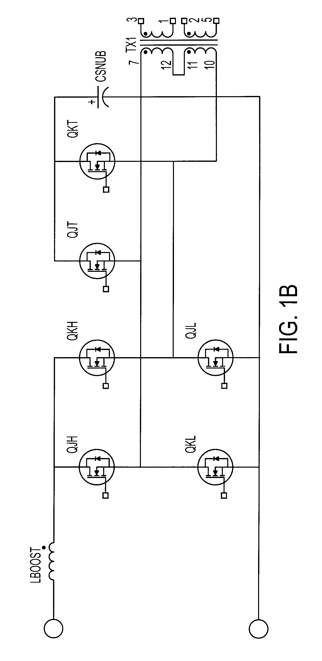
[0024]According to some other embodiments, a method of active regeneration control is performed that includes employing a comparator circuit with feedback from current-fed PI control to select one of two regeneration times of at least one active clamp: i) wherein at low loads a regeneration circuit is turned ON for substantially an entire current-transfer cycle such as to avoid output of current-fed converter continuing to rise; and ii) wherein at high loads the regeneration period is reduced to between about ¼ to ½ of a resonance-frequency cycle so that a resonance between the regeneration capacitance and the transformer's leakage inductance avoids excessive ringing currents and / or lost efficiency.

Problems solved by technology

For example, computer servers, computer networks, telecommunications electronics and medical devices are often powered by an uninterruptible power supply.
However, limiting stresses on semiconductor switching components of the bridge is an inherent challenge in such a topology.

Method used


Image

  • Active clamp resonance control
  • Active clamp resonance control
  • Active clamp resonance control

Examples


Embodiment Construction

[0037]While the present invention may be embodied in many different forms, there is described here detailed illustrative embodiments with the understanding that the present disclosure is to be considered as an example of the principles of the invention and is not intended to limit the invention to the illustrated embodiments.

[0038]Embodiments of the invention can be employed within, e.g., a modular UPS system, such as, e.g., that produced by TOSHIBA INTERNATIONAL CORPORATION, INC. In some embodiments, a power module includes two major components. A first component plugs into a connector and comprises the inverter. A second component is the converter, which accepts the AC in or a battery input, and then isolates and converts it to a DC bus voltage and regulates it. In some embodiments, both the inverter and the converter slide into a plastic module, and the module then slides onto a chassis.

[0039]In the preferred embodiments, aspects of the present invention are employed within a mod...


PUM


Abstract

According to some preferred embodiments, power converter includes a comparator circuit with feedback from current-fed PI or PID control to select one of two regeneration times of at least one active clamp: i) wherein at low loads a regeneration circuit is turned ON for substantially an entire current-transfer cycle such as to avoid output of current-fed converter continuing to rise; and ii) wherein at high loads the regeneration period is reduced to between about ¼ to ½ of a resonance-frequency cycle so that a resonance between the regeneration capacitance and the transformer's leakage inductance avoids excessive ringing currents and / or lost efficiency.

Description

BACKGROUND OF THE INVENIION[0001]1. Field of the Invention[0002]The present invention generally relates to power conversion circuits, and the preferred embodiments provide improved power conversion circuits for e.g., uninterruptible power supplies.[0003]2. Background Discussion[0004]Uninterruptible power supplies (UPSs) are commonly used to provide power to critical equipment that must not experience even short duration brownouts or blackouts. For example, computer servers, computer networks, telecommunications electronics and medical devices are often powered by an uninterruptible power supply.[0005]A UPS device typically has an AC-DC-AC converter and backup battery that is activated in case the alternating current (AC) line power is temporarily disconnected or falls below a voltage threshold.[0006]FIG. 5 shows one illustrative and non-limiting conventional UPS circuit according to the background art. The illustrated conventional UPS circuit includes an input rectifier (having swit...

Claims


Application Information

Patent Timeline
Patent Type & Authority Patents(United States)
IPC IPC(8): H02M3/335H02M3/337H02M3/338
CPCY02B70/1433H02M2001/342H02M3/337H02M1/34Y02B70/1491Y02B70/10H02M1/342H02M3/33573H02M3/01
Inventor WESTMORELAND, DAVIDAMBO, TATSUAKI
Owner TOSHIBA INT
Learn More