
Cleaning of cathode-ray tube display

a cathode-ray tube and display technology, applied in the field of cathode-ray tube cleaning, can solve the problem that the inherent capability of the display to remove contaminant material from the electron-emitting device is quite low, and achieve the effect of reducing the likelihood of dislodged contaminant material returning

Inactive Publication Date: 2005-03-29
CANON KK
View PDF18 Cites 0 Cited by
  • Summary
  • Abstract
  • Description
  • Claims
  • Application Information

AI Technical Summary

Benefits of technology

The pressure (or density) of gas inside a flat-panel CRT display is normally made low for two main reasons: (1) to avoid interfering with the flow of electrons from the display's electron-emitting device to the display's light-emitting device and (2) to avoid contaminating the electron-emitting and light-emitting devices. While inert gases do have some chemical reactivity, the level of chemical reactivity of an inert gas compared to a typical non-inert element or compound is generally so low that the presence of inert gas inside a flat-panel CRT display does not usually cause appreciable contamination of the display's electron-emitting and light-emitting devices. Hence, the second reason for avoiding gas inside a flat-panel CRT display generally does not apply to inert gases.
The present CRT display preferably includes a reservoir for supplying inert gas to the open space of the display's sealed enclosure. The reservoir replaces inert gas which lodges in the electron-emitting device (or elsewhere) during the ion-bombardment process and is effectively lost during display operation. As a result, the CRT display of the invention can maintain an adequate level of contaminant-removal capability and substantially avoids the loss of contaminant-removal capability which occurs with operational time in a conventional CRT display. When the present display includes the inert-gas reservoir, the partial pressure of all the inert gas in the sealed enclosure is at least 5×10⁻⁷ torr. The minimum partial pressures given above for helium, for argon, and for one or more of neon, krypton, xenon, and radon, generally apply to the situation in which the inert-gas reservoir is employed in the display except that the minimum partial pressure of argon is slightly lower, typically as little as 1×10⁻⁵ torr.
The CRT display of the invention also preferably includes a getter for collecting non-inert material. The getter collects contaminant material dislodged from the electron-emitting device and thereby prevents that material from re-contaminating the electron-emitting device. The getter is preferably positioned close to electron-emissive regions where display-damaging contaminant can accumulate so as to reduce the likelihood that dislodged contaminant material will return to those regions. For example, the getter can be distributed across the active electron-emitting portion of the electron-emitting device. Importantly, the getter normally does not collect inert gas to a significant degree and therefore does not cause the ion-bombardment self-cleaning capability of the invention to degrade significantly with time.
In short, the present inert-gas cleaning technique is highly advantageous because it enables the electron-emitting device of a CRT display, especially one of the flat-panel type, to be cleaned subsequent to final display sealing. The invention thus provides an important and substantial advance.

Problems solved by technology

However, the partial pressure of the inert gas inside a conventional CRT display is normally quite low so that the display's inherent capability for removing contaminant material from the electron-emitting device is quite low.

Method used


Image

  • Cleaning of cathode-ray tube display
  • Cleaning of cathode-ray tube display
  • Cleaning of cathode-ray tube display

Examples


Embodiment Construction

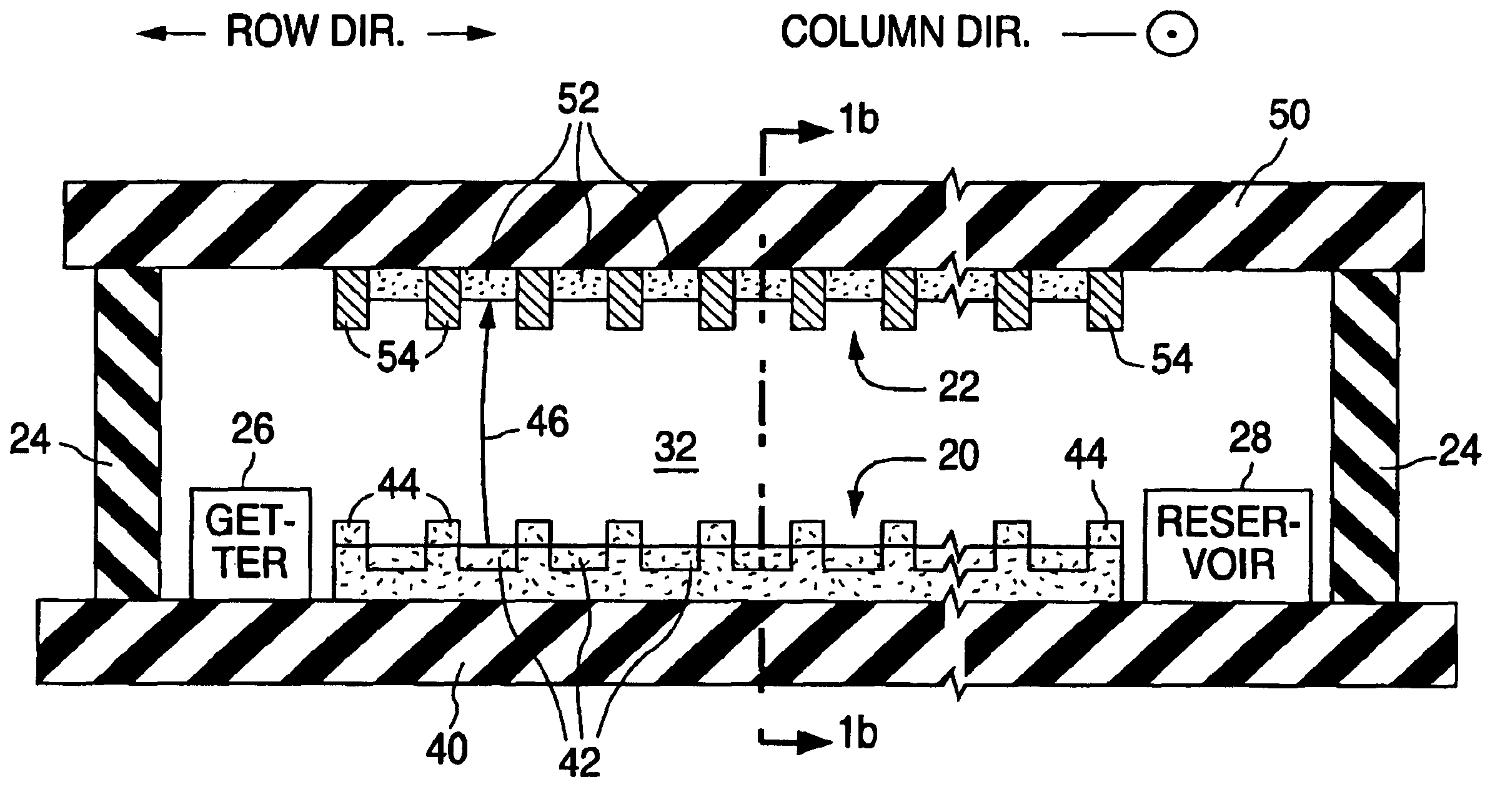
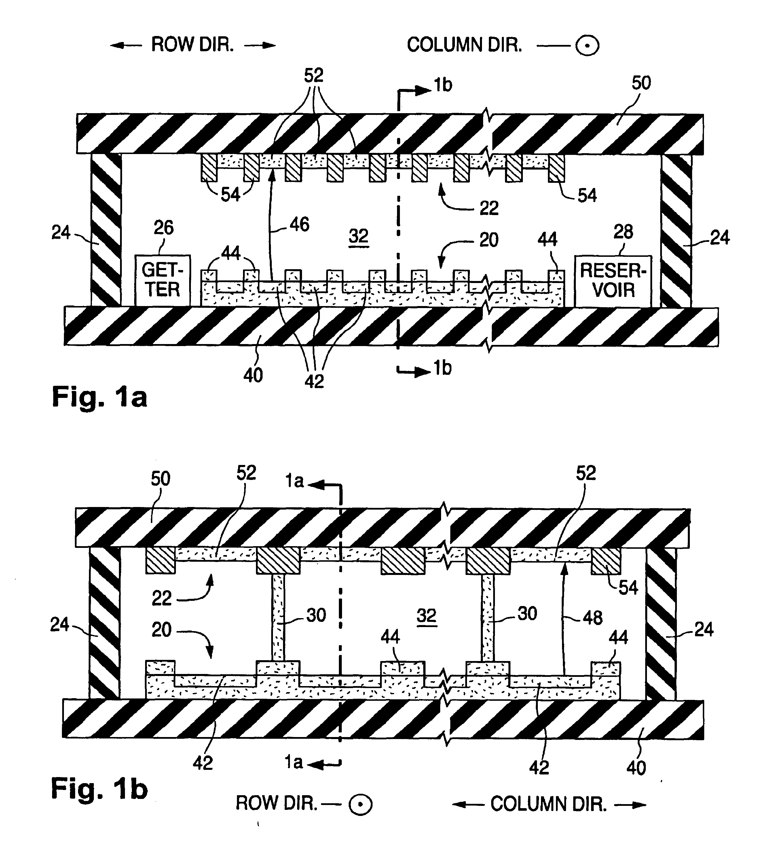
A flat-panel CRT display having a built-in capability, in accordance with the invention, for automatically cleaning the display's electron-emitting device during normal display operation is described below. The present flat-panel CRT display is typically suitable for a flat-panel television or a flat-panel video monitor for a personal computer, a laptop computer, a workstation, or a hand-held device such as a personal digital assistant.

A flat-panel CRT display whose electron-emitting device is cleaned according to the invention is typically a color display but can be a monochrome, e.g., black-and-white or black-and-green, display. Each electron-emissive region and the corresponding oppositely positioned light-emissive region form a pixel in a monochrome display, and a sub-pixel in a color display. A color pixel typically consists of three sub-pixels, one for red, another for blue, and the third for green.

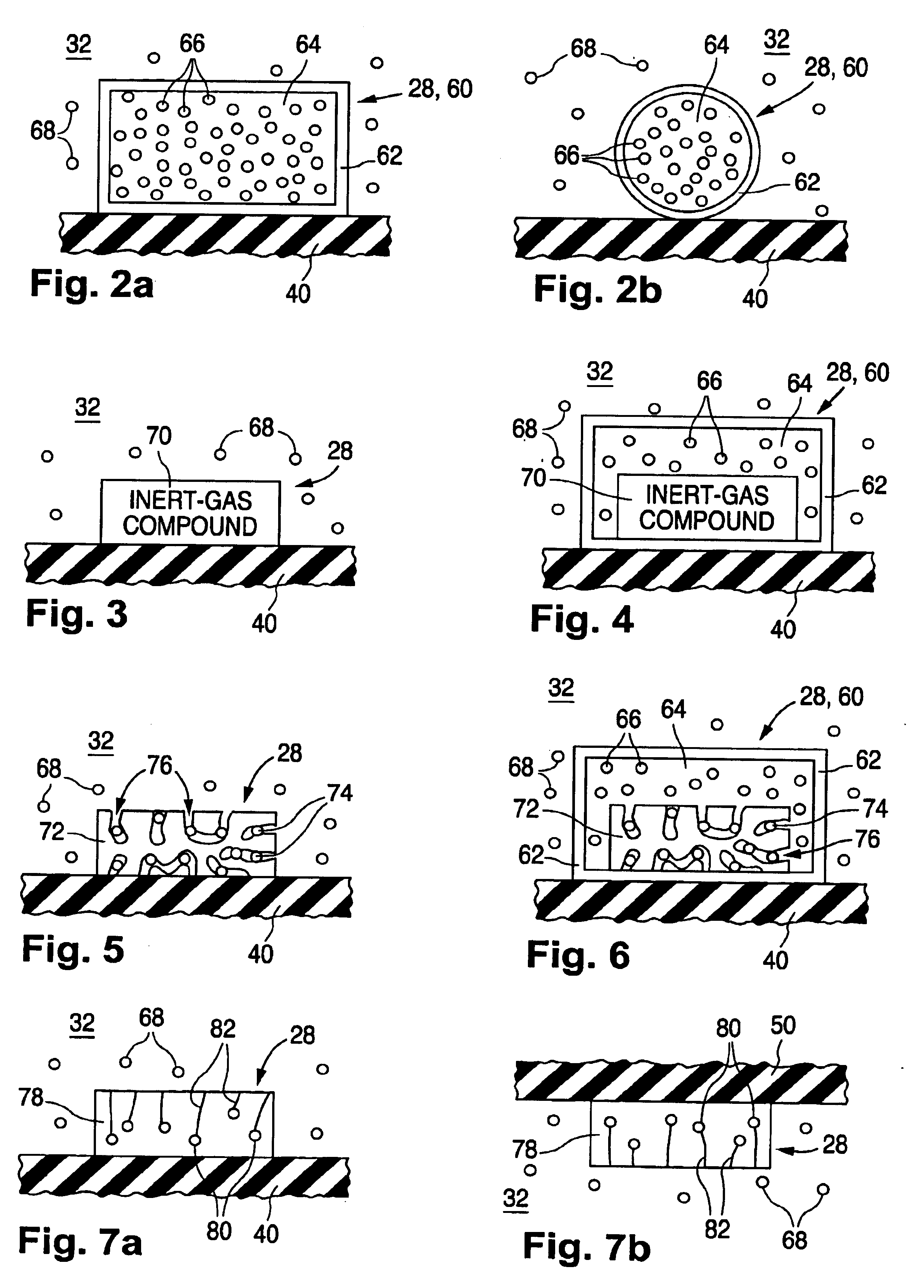
In the following description, the term “electrically insulating” or “dielectric...


PUM


Abstract

Inert gas provided at a suitable level inside a hermetically sealed cathode-ray tube display, typically of the flat-panel type, enables the display's electron-emitting device (20) to be automatically cleaned during display operation subsequent to final display sealing. Upon being struck by electrons emitted by the electron-emitting device, atoms (68) of the inert gas ionize to produce positively charged ions (124) which travel backward to the electron-emitting device and dislodge overlying contaminant material (130 and 132). A getter (26) collects dislodged contaminant. A reservoir (28) provides inert gas to replace inert gas lost during the cleaning process.

Description

FIELD OF USEThis invention relates to cathode-ray tube (“CRT”) displays, especially CRT displays of the flat-panel type.BACKGROUNDA flat-panel CRT display basically consists of an electron-emitting device and a light-emitting device that operate at low internal pressure, typically from 10−6 torr to 10−2 torr. The electron-emitting device, commonly referred to as a cathode, contains electron-emissive elements allocated into a group of laterally separated electron-emissive regions for emitting electrons over a relatively wide area. The emitted electrons are directed towards light-emissive regions distributed over a corresponding area in the light-emitting device. Upon being struck by the electrons, the light-emissive regions emit light that produces an image on the viewing surface of the display.The electron-emissive elements need to be clean during display operation. Contaminants that build up on the surfaces of the electron-emissive elements act to increase the height and / or width o...

Claims


Application Information

Patent Timeline
IPC IPC(8): H01J29/94H01J29/00
CPCH01J29/94
Inventor PEI, SHIYOUSTANNERS, COLIN D.BYERS, FREDERICK K.
Owner CANON KK
Learn More