Subcarrier multiplexing type optical communication method and passive optical network using the same

a passive optical network and multi-carrier technology, applied in the field of optical communication networks, can solve the problems of increasing the cost of installing and maintaining the network, affecting the performance of the network, and causing optical interference, so as to minimize optical beat interference

Active Publication Date: 2014-03-25
SAMSUNG ELECTRONICS CO LTD
View PDF12 Cites 0 Cited by
  • Summary
  • Abstract
  • Description
  • Claims
  • Application Information

AI Technical Summary

Benefits of technology

[0016]Accordingly, the present invention has been made to solve the above-mentioned problems occurring in the prior art and provides additional advantages, by providing a subcarrier-type passive optical network capable of minimizing optical beat interference.

Problems solved by technology

However, when upstream subcarrier channels having the same wavelength are detected by a single upstream receiver, interference between them may lead to optical interference.
The resulting interference between subcarrier channels creates subcarrier frequencies.
Removing this interference increases the cost for installing and maintaining the network.

Method used


Image

  • Subcarrier multiplexing type optical communication method and passive optical network using the same
  • Subcarrier multiplexing type optical communication method and passive optical network using the same
  • Subcarrier multiplexing type optical communication method and passive optical network using the same

Examples


first embodiment

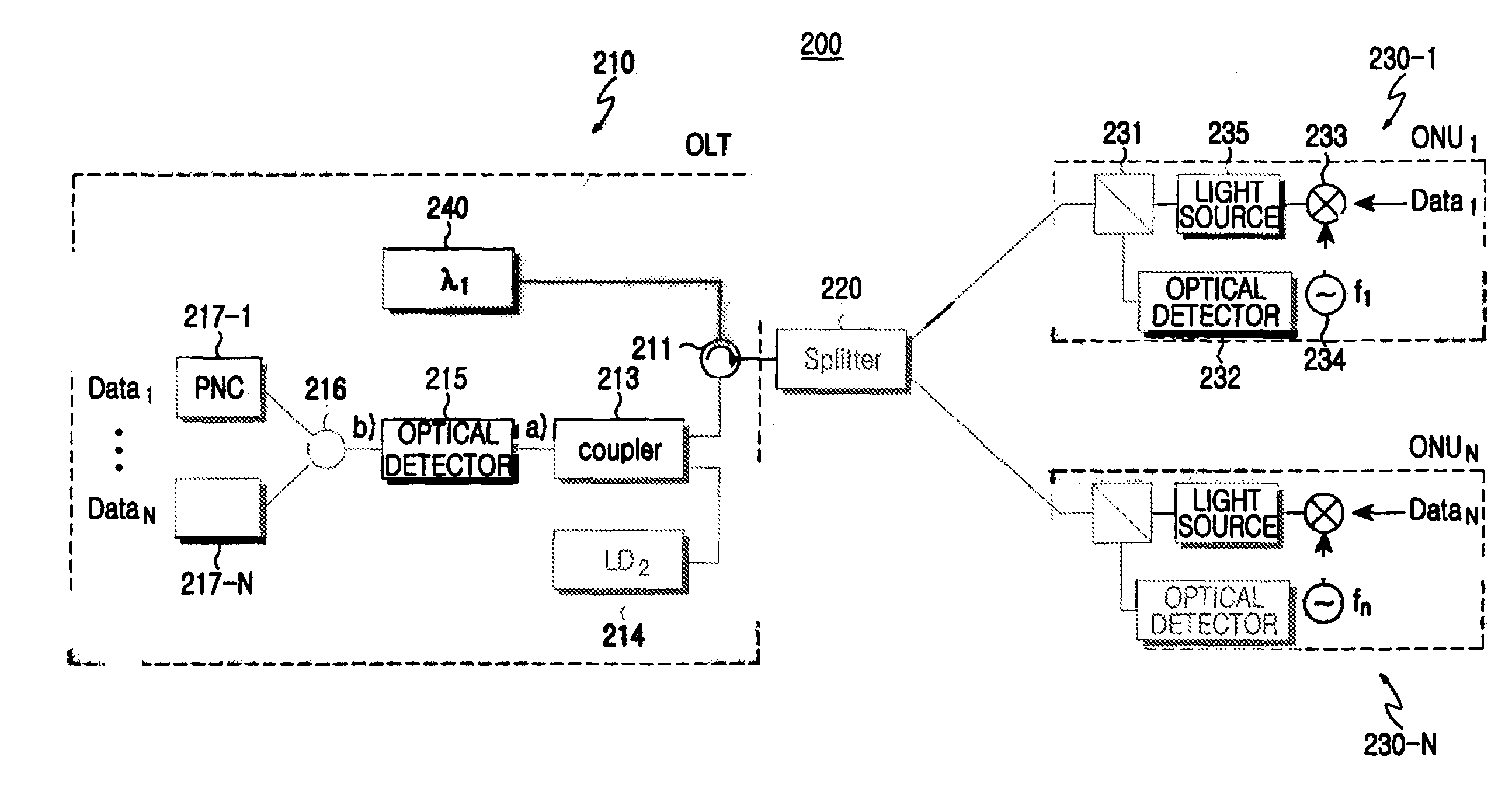
[0055]FIG. 3 shows a subcarrier multiplexing type passive optical network according to the present invention. Referring to FIG. 3, the passive optical network 200 includes an optical line terminal 210 for detecting data from a plurality of upstream subcarrier channels and creating a downstream optical signal consisting of downstream subcarrier channels having respective proper frequencies, a plurality of optical network units 230-1 to 230-N for detecting data from the downstream subcarrier channels having respective frequencies allocated thereto and creating upstream subcarrier channels, and a remote node (splitter) 220 positioned between the optical network units 230-1 to 230-N and the optical line terminal 210.

[0056]The optical line terminal 210 includes a light creation unit 240 for creating a single wavelength of downstream optical signal loaded with a plurality of downstream subcarrier channels having respective proper frequencies, a light source 214, an optical coupler 213, an...

second embodiment

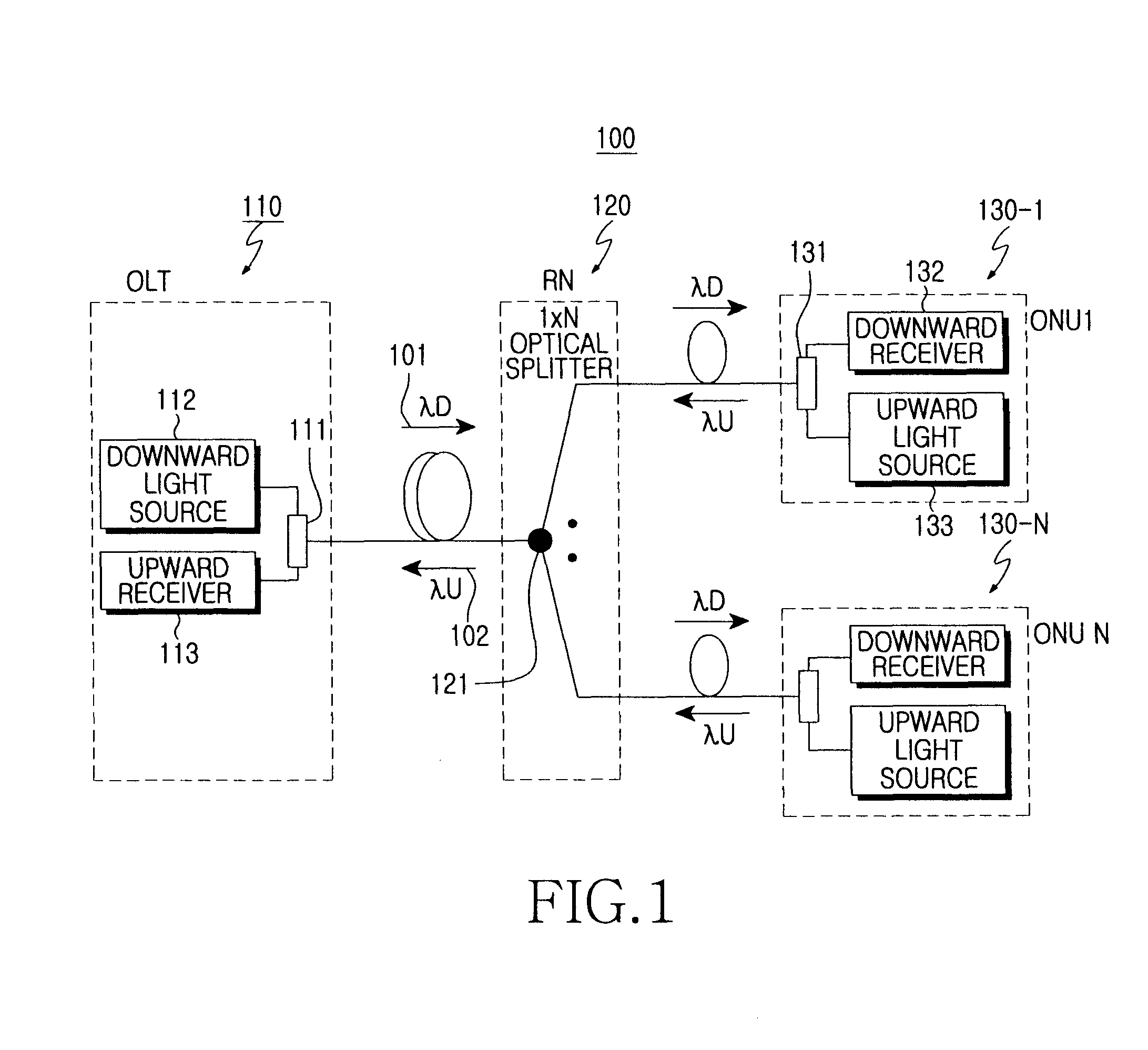
[0065]FIG. 7 shows the construction of a passive optical network according to the present invention. The passive optical network 500 according to the present embodiment includes an optical line terminal 510 for creating multiplexed downstream optical signals having different wavelengths and detecting data from multiplexed upstream optical signals, a plurality of optical network units 560-1 to 560-N for detecting data from a downstream subcarrier channel having a corresponding frequency and creating an upstream subcarrier channel having a corresponding frequency, and remote nodes 540, 550-1 to 550-N positioned between the optical network units 560-1 to 560-N and the optical line network 510.

[0066]The optical line terminal 510 includes a plurality of light sources 522- to 522-N for creating downstream optical signals having different wavelengths, which consist of a plurality of downstream subcarrier channels having different frequencies, a multiplexer 521 for multiplexing the downstre...


PUM


Abstract

Disclosed is a subcarrier multiplexing type optical communication method including the steps of receiving a first optical signal composed of a plurality of subcarrier channels having different frequencies, creating a second optical signal having a wavelength different from a wavelength of a received signal; and detecting the subcarrier channels from a third optical signal obtained by subjecting the first optical signal to wavelength shift by means of the second optical signal.

Description

CLAIM OF PRIORITY[0001]This application claims the benefit of the earlier filing date, pursuant to 35 USC 119(e), to that patent application entitled “Subcarrier Multiplexing Type Optical Communication Method and Passive Optical Network Using the Same” filed with the Korean Intellectual Property Office on May 2, 2006 and assigned Serial No. 2006-39607, the contents of which are incorporated herein by reference.BACKGROUND OF THE INVENTION[0002]1. Field of the Invention[0003]The present invention relates to an optical communication network, and more particularly to a subcarrier-type passive optical network.[0004]2. Description of the Related Art[0005]Optical networks are being more widespread, as they are suitable for various multimedia services based on extensive use of Internet and broadband signal transmission. The optical networks are typically used in-line with FTTx (Fiber To The x) technology for guaranteeing Gigabit per second (Gbps)-grade transmission speed by using optical fi...

Claims


Application Information

Patent Timeline
Patent Type & Authority Patents(United States)
IPC IPC(8): H04J14/02H04B10/272
CPCH04J14/0298H04J14/0282H04J14/0252H04J14/0246H04J14/0226H04J14/025H04J2014/0253H04J14/0247H04B10/25H04B10/00
Inventor JUNG, DAE-KWANGHWANG, SEONG-TAEKPARK, JIN-WOOLEE, SANG-LOKLEE, SUNG-KUEN
Owner SAMSUNG ELECTRONICS CO LTD
Why Eureka
Try Eureka