
System and method for broadband RF interference cancellation

a technology of broadband rf interference and system and method, applied in the field of system and method for broadband rf interference cancellation, can solve the problem of annihilation of optical signals rather than adding to quiescent dc optical levels, and achieve the effect of reducing interferen

Active Publication Date: 2014-03-25
THE TRUSTEES FOR PRINCETON UNIV
View PDF100 Cites 27 Cited by
  • Summary
  • Abstract
  • Description
  • Claims
  • Application Information

AI Technical Summary

Benefits of technology

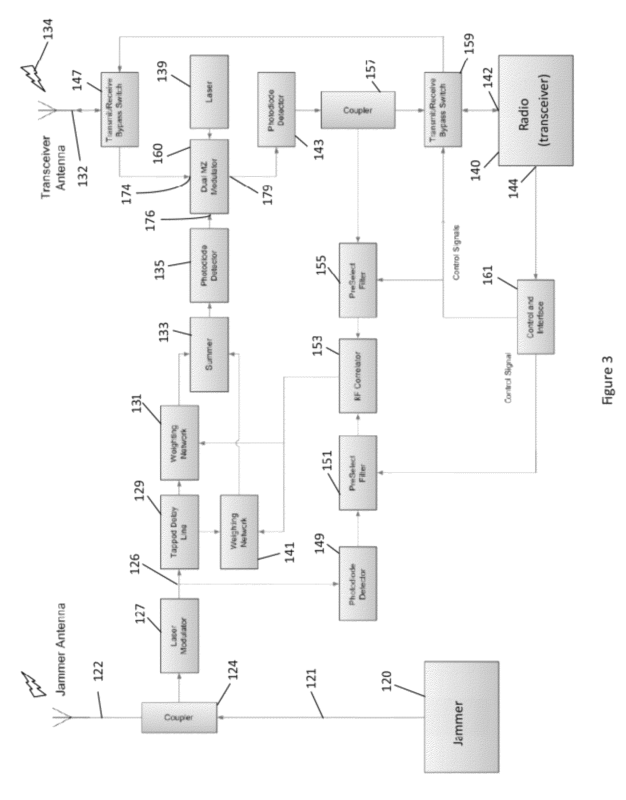
This patent text describes a system and method for reducing interference in RF communication equipment that may be located close to each other or remote from each other. The system uses a dual parallel electrical RF signal to optical signal converter to create a cancelled interference optical signal through destructive interference. The advantages of this system include improved signal-to-noise ratio, increased linearity and dynamic range, and the elimination of a specific problem called the S21 mismatch. The text also mentions that matched filtering can be done electrically between the transmitted and received signals.

Problems solved by technology

The result is annihilation of the optical signal rather than adding to a quiescent DC optical level.

Method used


Image

  • System and method for broadband RF interference cancellation
  • System and method for broadband RF interference cancellation
  • System and method for broadband RF interference cancellation

Examples


Embodiment Construction

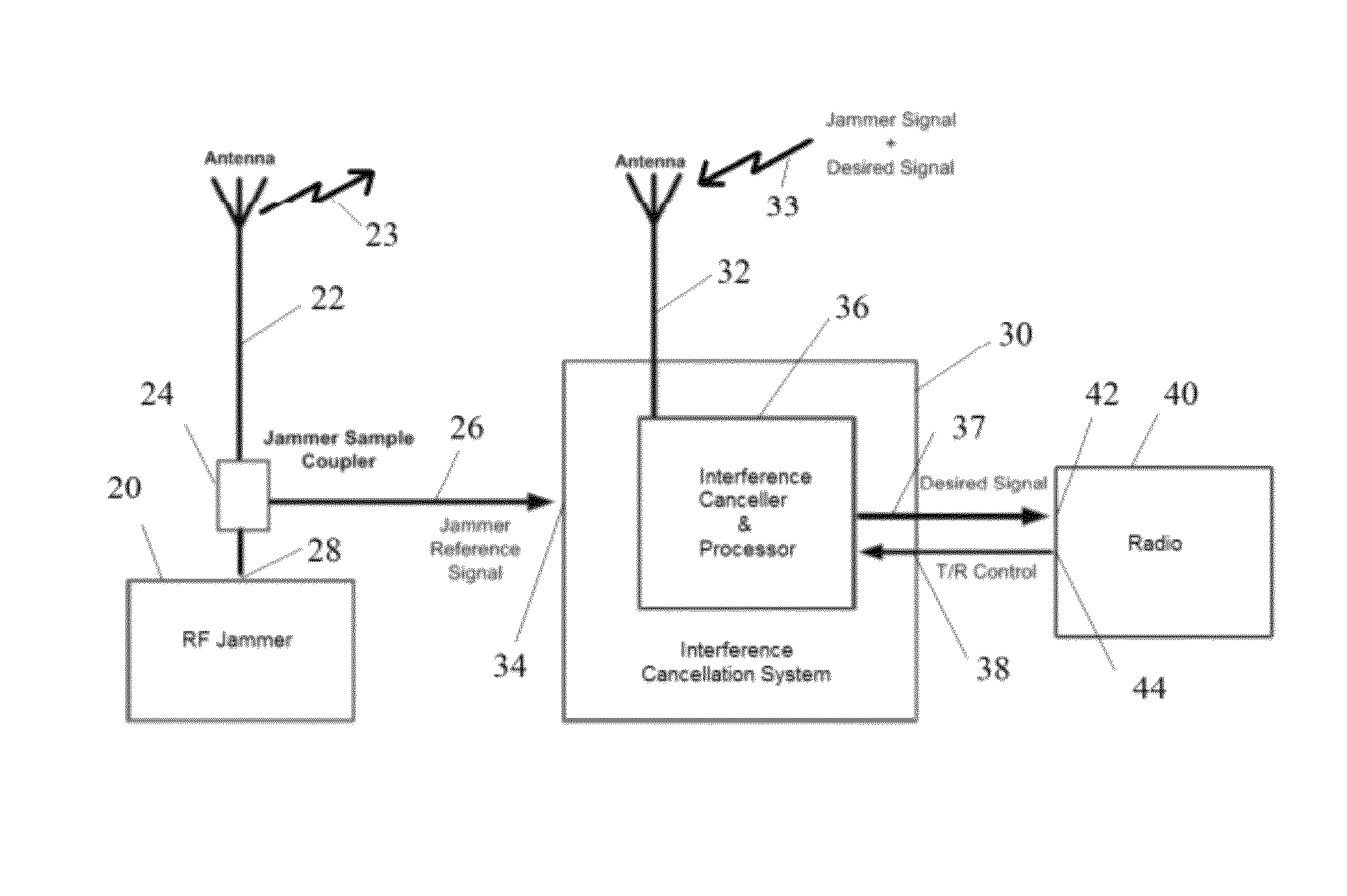
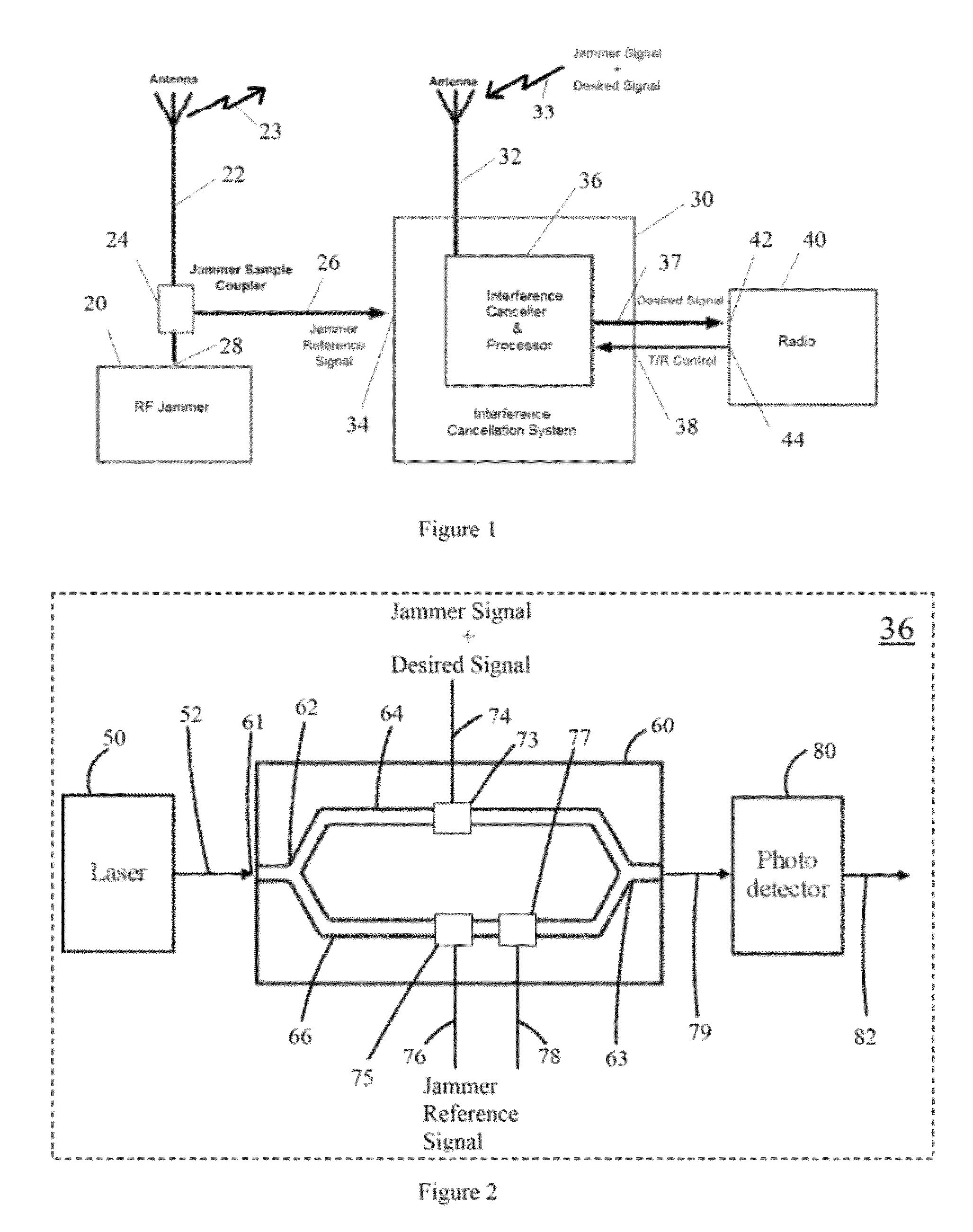
[0012]Disclosed is a system and method that allows co-located and / or remote interferers and communication equipment to operate in harmony. FIG. 1 is a schematic of an example system architecture and illustrates the relationship between a radio frequency (RF) interferer 20, interference cancellation system (ICS) 30 and radio 40. Power sources for these devices are not shown for purposes of clarity. The provision of appropriate power for such devices, e.g., AC or DC power, from the power grid batteries or other sources, is well known to those skilled in the art. The examples disclosed herein focus on the radio 40 receive functionality. However, it should be understood that the radio 40 may be capable of both transmit and receive functionality. The ICS 30 is configured to substantially reduce jamming interference that cannot be removed by known radio receiver RF front end filters.

[0013]The RF interferer 20 includes an interferer antenna 22 configured to transmit an interferer signal sh...


PUM


Abstract

Radio frequency transmission systems often suffer from the problem of co-site interference, where the frequency band of a strong radio transmitter overlaps with the frequency band of a co-located and / or remote radio receiver, such that the transmitter interferes with the ability of the receiver to detect a weak signal of interest. There is a need for a device that can process both the transmitted radio signal and the received radio signal to eliminate such interference. Previous attempts to solve this problem have been unable to cancel in-band interference in excess of 20 to 40 dB stronger than the signal of interest over a broad bandwidth, with large dynamic range, and with a high degree of linearity. Disclosed is a robust system and method for cancelling broadband in-band RF interference that operates in a dynamically changing multipath environment.

Description

CROSS-REFERENCE TO PRIOR FILED APPLICATION[0001]This application claims priority to earlier filed U.S. provisional patent application No. 61 / 488,521 filed on May 20, 2011, which is herein incorporated by reference in its entirety.UNITED STATES GOVERNMENT RIGHTS[0002]This invention was made with government support under Subaward #96183NBS68 from Booz Allen Hamilton, Inc. to Princeton University (PRIME: U.S. Army, Grant #W15P7T-06-D-E401) and Subaward #S12-119176 from CACI Technology, Inc. to Princeton University (PRIME: U.S. Army—Fort Monmouth, Grant #TESS W15P7T-09-D-P013). The government has certain rights in this invention.FIELD OF INVENTION[0003]The present disclosure generally relates to a new system and method for broadband RF interference cancellation that will allow co-located and / or remote interferers and communication equipment to operate in harmony.BACKGROUND[0004]Due to exponential growth in the demand for radio frequency (RF), the radio spectrum is extremely crowded and ...

Claims


Application Information

Patent Timeline
Patent Type & Authority Patents(United States)
IPC IPC(8): H04B10/00
CPCH04B1/109H04K3/228
Inventor PRUCNAL, PAUL
Owner THE TRUSTEES FOR PRINCETON UNIV
Learn More