Proximity detection device and proximity detection method

a technology of proximity detection and detection method, which is applied in the direction of resistance/reactance/impedence, instruments, complex mathematical operations, etc., can solve the problems of high computational cost, large amount of computation in the correlation computing unit, and difficulty in detecting the effect of proximity detection

Active Publication Date: 2014-03-25
RPX CORP
View PDF9 Cites 13 Cited by
  • Summary
  • Abstract
  • Description
  • Claims
  • Application Information

AI Technical Summary

Benefits of technology

[0025]According to the aspects of the invention, a proximity detection device and method that can successfully perform detection without crosstalk by simultaneously applying alternating voltages to plural transmitting electrodes even when driving at a relatively low voltage or operating at a high speed can be realized. When power supply voltage, the detection speed, and the frequencies of the alternating voltages are the same, a proximity detection device and method that can make the influence of noise smaller can be realized.

Problems solved by technology

However, in the case of the example shown in FIG. 8, detection efficiency has been problematic because of line-sequential driving.
In the above described conventional proximity device using multiline driving, there have been problems that the amount of computation in the correlation computing unit is large and a high-speed computer is necessary for higher detection speed.
Further, in the case where the patterns applied to the transmitting electrodes are not completely orthogonal, there has been a problem that crosstalk occurs in the correlation computation result.

Method used


Image

  • Proximity detection device and proximity detection method
  • Proximity detection device and proximity detection method
  • Proximity detection device and proximity detection method

Examples


embodiment

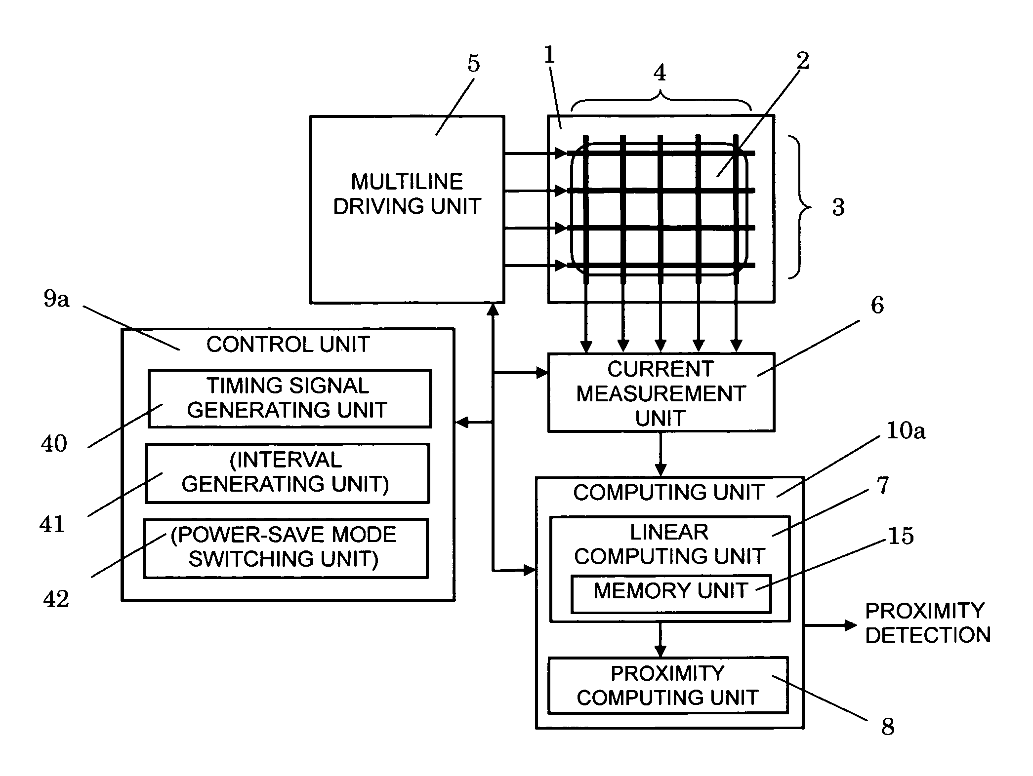
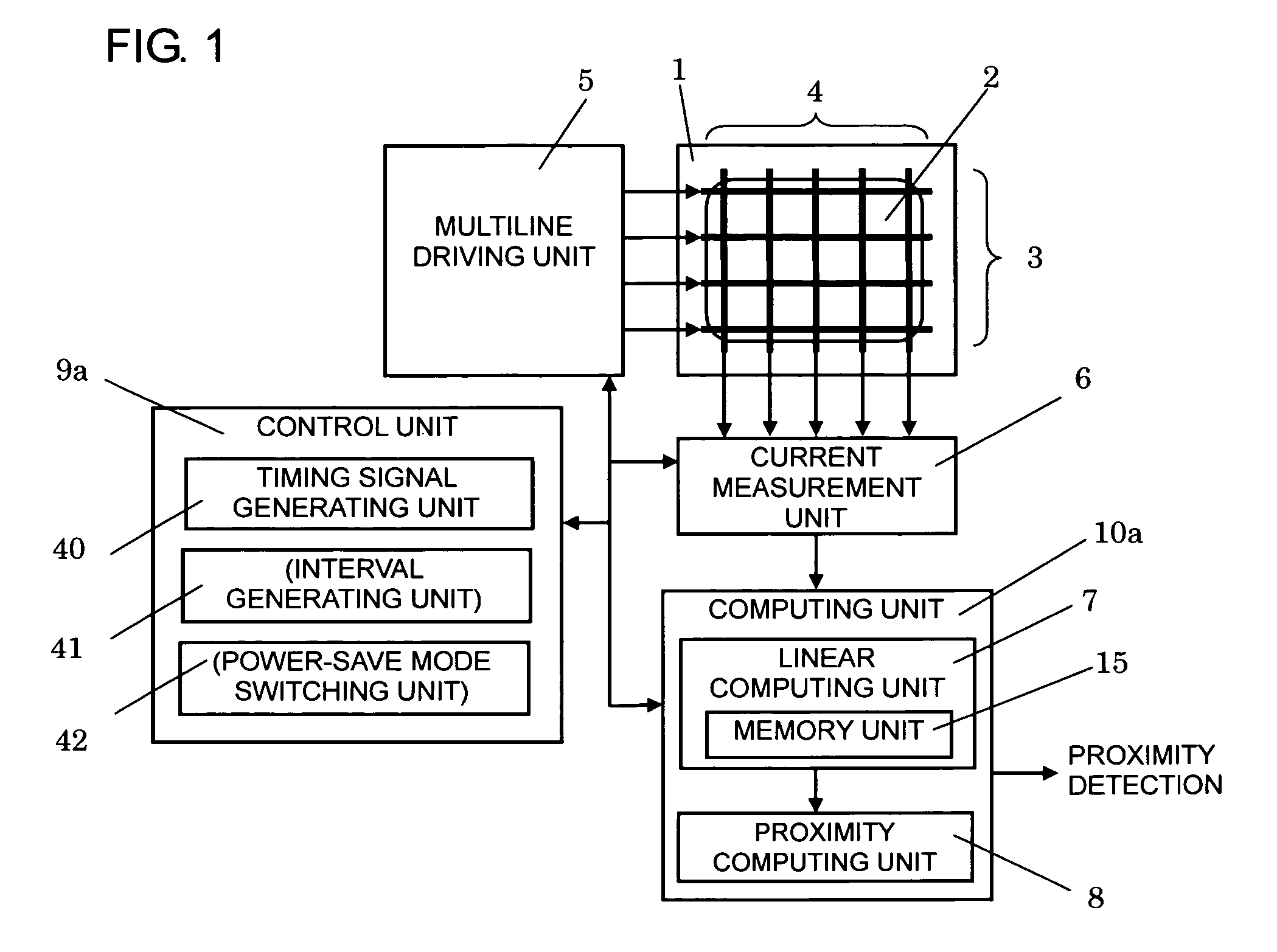
[0035]A preferred embodiment of the invention will be explained based on FIG. 1.

[0036]A proximity detection device according to the invention includes, in FIG. 1, transmitting electrodes 3 corresponding to one dimension of two dimensional coordinates in a detection area 2 on a supporting unit 1 and receiving electrodes 4 corresponding to the other dimension provided via insulating layers for preventing electric continuity between them, a multiline driving unit 5 that simultaneously applies periodic alternating voltages to plural electrodes of the transmitting electrodes 3, a current measurement unit 6 that measures the magnitudes of the currents from the receiving electrodes 4 changing in response to the electrostatic couplings of the intersections between the transmitting electrodes 3 and the receiving electrodes 4 in synchronization with the driving to the transmitting electrodes 3, a computing unit 10a that obtains an approach determination and an approach position of an object t...


PUM


Abstract

A proximity detection device has transmitting and receiving electrodes and a multiline driving unit that simultaneously applies periodic alternating voltages to at least two of the transmitting electrodes. A measurement unit measures currents or amounts of accumulated charge from the receiving electrodes in synchronization with the simultaneous application of periodic alternating voltages to the at least two transmitting electrodes by the multiline driving unit. A linear computing unit performs linear computation of measurement results from a measurement unit in response to electrostatic capacitances of respective intersections between the transmitting and receiving electrodes. The linear computing unit has a memory unit that stores an output of the linear computation for readout at plural times. A proximity computing unit performs a computation to determine an approach and / or a position of an object relative to a detection area based on the output from the linear computing unit stored in the memory unit.

Description

BACKGROUND OF THE INVENTION[0001]1. Field of the Invention[0002]The present invention relates to a proximity detection device for detecting an approach and a position of an object by a human finger or the like by changes in electrostatic capacitances of respective intersections of plural electrodes arranged in correspondence with two-dimensional coordinates.[0003]2. Description of the Related Art[0004]It is known that, when an object of a human finger or the like approaches between two closely located electrodes, the electrostatic capacitance between the electrodes changes. Proximity detection devices such as an electrostatic touch sensor to which the principle is applied to the detection of the electrostatic capacitances of respective intersections of plural electrodes arranged in correspondence with two-dimensional coordinates in a detection area have been disclosed, and some of them have been put into practical use (for example, see JP-T-2003-526831).[0005]An example of the conve...

Claims


Application Information

Patent Timeline
Patent Type & Authority Patents(United States)
IPC IPC(8): G06F17/14
CPCG06F3/0416G06F3/044G06F3/04166G06F3/0446
Inventor MATSUSHIMA, KENICHI
Owner RPX CORP
Why Eureka
Try Eureka