Fan module

a technology of fan module and fan body, which is applied in the direction of machines/engines, liquid fuel engines, instruments, etc., can solve the problems that the cooling fans of both the axial flow type and the blower type cannot meet the cooling needs of small-size electronic products, and achieve the effect of improving the cooling

Active Publication Date: 2014-04-01
SUNONWEALTH ELECTRIC MACHINE IND
View PDF16 Cites 14 Cited by
  • Summary
  • Abstract
  • Description
  • Claims
  • Application Information

AI Technical Summary

Benefits of technology

[0011]It is therefore the primary objective of this invention to provide a fan module capable of drawing in external air from two different directions. Thus, when the fan module is mounted in various electronic products, the fan module not only can draw the external air into the electronic products for cooling purposes, but also can expel the hot air from the electronic products for an improved cooling effect.
[0012]It is therefore another objective of this invention to provide a fan module having an impeller capable of separating air currents coming from two different directions to avoid turbulence.
[0013]It is therefore another objective of this invention to provide a fan module having an impeller capable of drawing in external air from different directions and separating air currents, to reduce the axial height of the fan module.

Problems solved by technology

However, these conventional cooling fans of both the axial-flow type and the blower type can not fulfill the cooling needs in small-size electronic products, such as notebook computers, mobile phones, and personal digital assistants, having a developing trend of miniaturization and having higher operating speeds.

Method used


Image

  • Fan module
  • Fan module
  • Fan module

Examples


Embodiment Construction

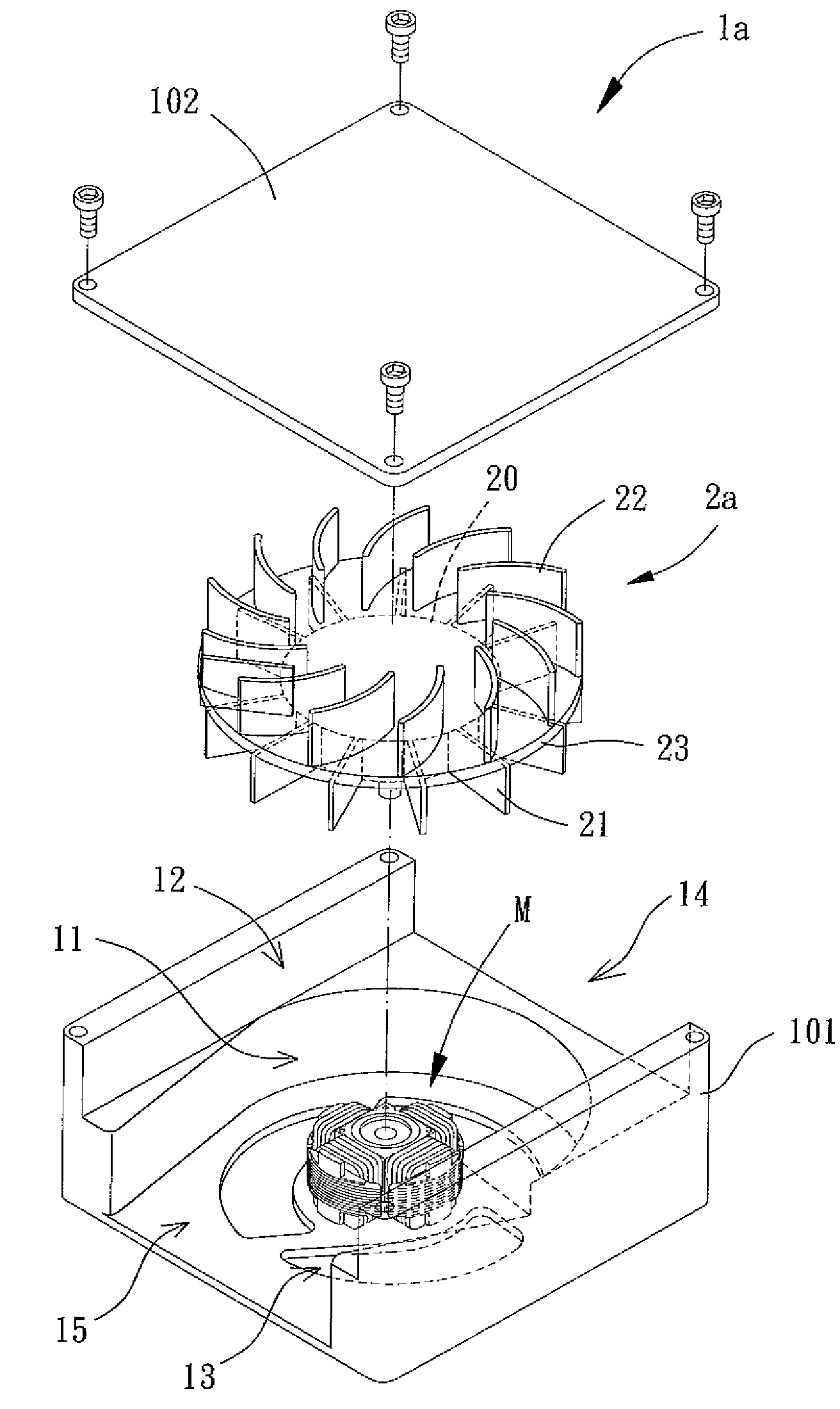
[0029]With reference to FIG. 3, a fan module according to the present invention includes a housing 1 and an impeller 2. The housing 1 can be of any form and shape for receiving the impeller 2. The impeller 2 is mounted in the housing 1 for not only drawing in air currents in different directions to provide a predetermined cooling effect, but also for separating the air currents drawn in the two different directions.

[0030]The housing 1 includes a first air channel 11 and a second air channel 12. The housing 1 further includes an axial air inlet 13, a radial air inlet 14 and at least one radial air outlet 15. FIG. 4 shows an example having two radial air outlets 15. The axial air inlet 13 is in communication with the first air channel 11. The radial air inlet 14 is in communication with the second air channel 12. The at least one radial air outlet 15 is in communication with the first and second air channels 11 and 12.

[0031]The impeller 2 can be of any member that can be driven to rot...


PUM


Abstract

A fan module includes a housing and an impeller. The housing has an axial air inlet, a radial air inlet and at least one radial air outlet. The impeller is rotatably disposed in the housing and has a first air-guiding blade, a second air-guiding blade and a partitioning member. The partitioning member separates an interior space of the housing into a first air channel and a second air channel. The first air-guiding blade is located in the first air channel, and the second air-guiding blade is located in the second air channel.

Description

BACKGROUND OF THE INVENTION[0001]1. Field of the Invention[0002]The present invention relates to a fan module and, more particularly, to a fan module that can draw in air currents from different directions and separate the drawn air currents.[0003]2. Description of the Related Art[0004]Conventional cooling fans generally include an axial-flow type and a blower type. Axial-flow type cooling fans include an axial air inlet and an axial air outlet spaced from the axial air inlet in an axial direction. Air can be drawn in via the axial air inlet and exit via the axial air outlet to provide cooling effect. Blower type cooling fans include an axial air inlet in an axial direction and a radial air outlet in a radial direction. Air can be drawn in via the axial air inlet and exit via the radial air outlet to provide a cooling effect.[0005]Generally, conventional cooling fans of both the axial-flow type and the blower type can be used in various electronic products to prolong the service liv...

Claims


Application Information

Patent Timeline
Patent Type & Authority Patents(United States)
IPC IPC(8): F04D29/44
CPCF04D17/162F04D17/04F04D25/166G06F1/20H05K7/20
Inventor HORNG, ALEXCHEN, WEN-KUAN
Owner SUNONWEALTH ELECTRIC MACHINE IND
Why Eureka
Try Eureka