Fuel tank for vehicle

a fuel tank and vehicle technology, applied in the direction of machines/engines, rigid containers, transportation items, etc., can solve the problems of serious damage to the engine, blockage of the fuel injection and lubricating system, failure of the engine, etc., to improve the recovery efficiency of carbon dioxide, facilitate the replacement of air, and improve the effect of fuel efficiency

Inactive Publication Date: 2014-04-01
HINO MOTORS LTD
View PDF18 Cites 5 Cited by
  • Summary
  • Abstract
  • Description
  • Claims
  • Application Information

AI Technical Summary

Benefits of technology

[0020]According to a fuel tank for a vehicle of the invention, various excellent advantages can be obtained as follows.
[0021](I) The interior of the tank body can be kept in an inert atmosphere without requiring large-scale equipment components such as an oxygen / nitrogen separating device, a nitrogen gas cylinder (and an oxygen gas cylinder) and a piping system. Moreover, the filling of the tank body with an inert gas containing plenty of carbon dioxide can be conducted without motive power by use of the negative pressure due to reduction of the fuel in the tank body, so that the interior of the tank body can be reliably kept in an inert atmosphere without impairing vehicle mountability and without requiring an energy consumption which deteriorates fuel efficiency.
[0022](II) Construction may be such that the carbon dioxide permeable membrane is cylindrically formed to secure an air flow path centrally of the cylindrical membrane and a carbon dioxide collecting chamber is formed on the outer periphery of the cylindrical membrane and is connected with the breather. Such cylindrical formation of the carbon dioxide permeable membrane can widen a permeable area of the membrane with an outer shape of the membrane being compact in size, and allows air to freely come into and out of the flow path centrally of the cylindrical membrane to facilitate replacement of the air in the flow path with new air.
[0023](III) Configuration may be employed which includes a vacuum pump at the top of the tank body to suck and discharge the gas in the tank body through the check valve. Then, the vacuum pump can be operated to actively increase the negative pressure in the tank body so as to improve recovery efficiency of carbon dioxide. Thus, even if air invades the tank body during the supply of the fuel with the fuel cap being opened, the vacuum pump is operated with the fuel cap being closed after the supply of the fuel to improve the recovery efficiency of carbon dioxide, thereby purging residual oxygen in the tank body in a short time.
[0024](IV) Configuration may be employed which includes the opening / closing detecting means for detecting opening / closing of the fuel cap for closure of the fuel supply port of the tank body, the level meter for detecting a level of the fuel in the tank body and the controller for receiving signals from the level meter and the opening / closing detecting means to measure a gas amount in the tank body when the fuel cap is opened and for operating the vacuum pump to keep the interior of the tank body in an inert atmosphere when the fuel cap is closed. Then, the gas amount in the tank body is measured by the controller when the fuel cap is opened, and the vacuum pump is operated on the basis of the measurement value by the controller when the fuel cap is closed, thereby automatically purging residual oxygen in the tank body.

Problems solved by technology

There is concern that direct use of such fats, which have a feature of high viscosity among others, as they are as fuel for a diesel automobile would cause failure of an engine due to adhesion of deposits on a fuel pump.
When a vehicle with the biodiesel fuel in its fuel tank is left unused for a long time, the fuel in the tank may proceed to oxidization and deterioration to corrode the tank and / or produce polymers to cause clogging in fuel injection and lubricating systems, resulting in serious damages to the engine.

Method used


Image

  • Fuel tank for vehicle
  • Fuel tank for vehicle
  • Fuel tank for vehicle

Examples


Embodiment Construction

[0027]An embodiment of the invention will be described with reference to the drawings.

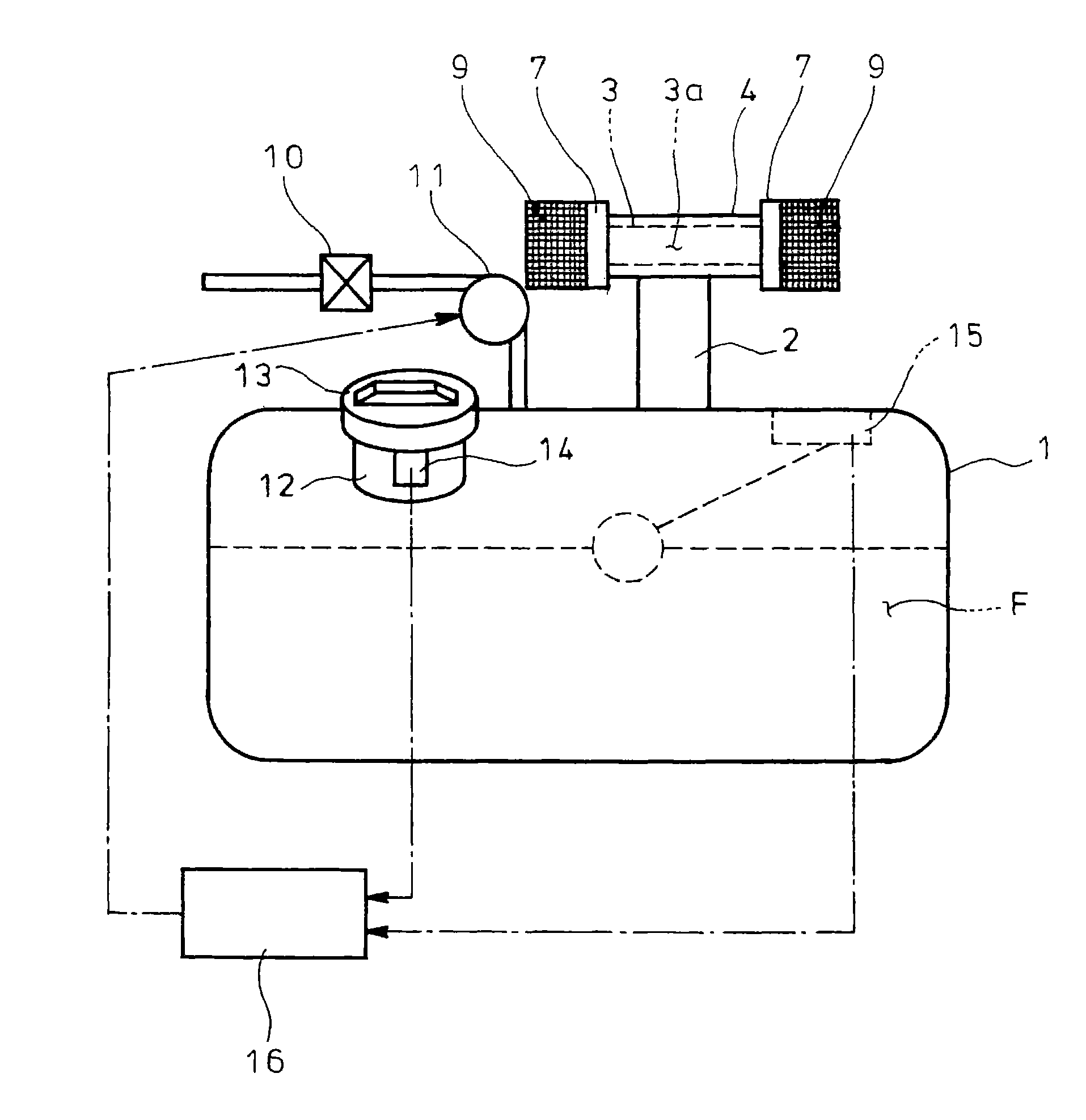
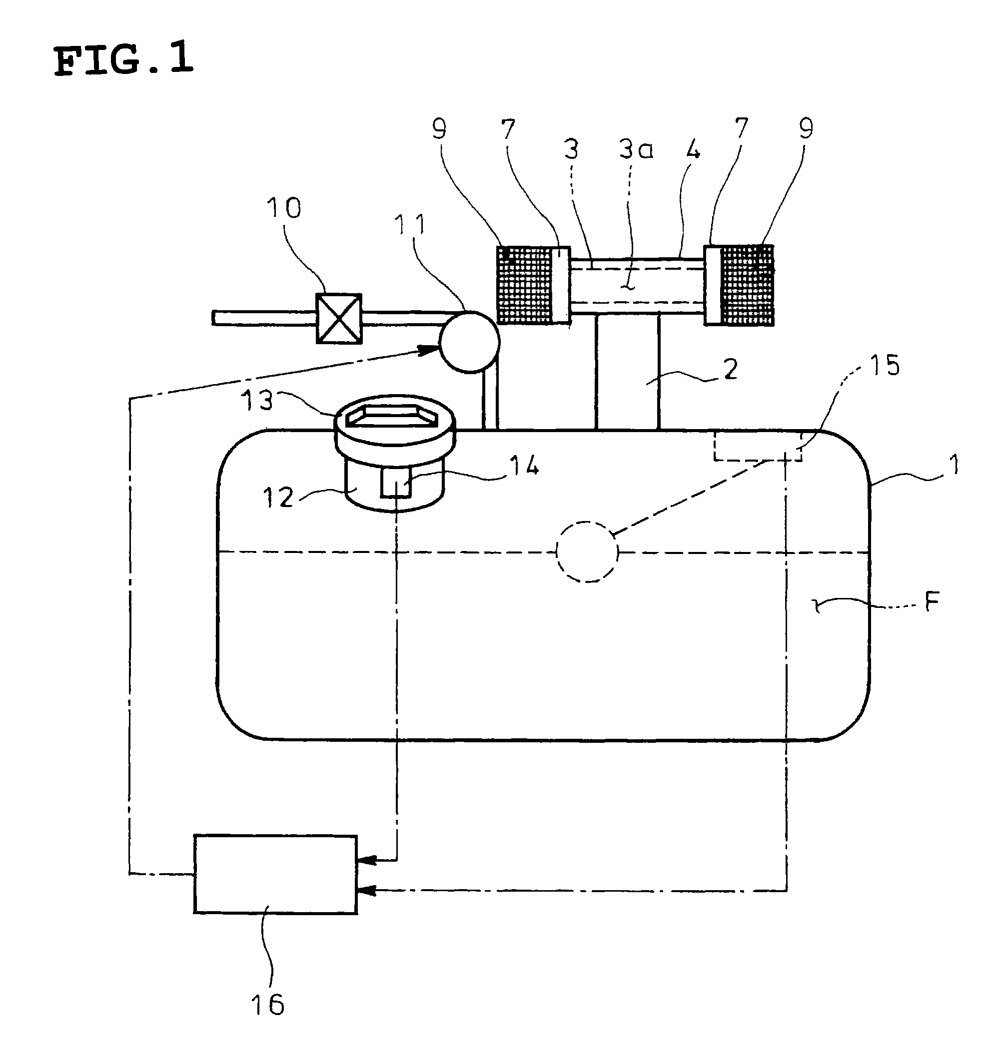
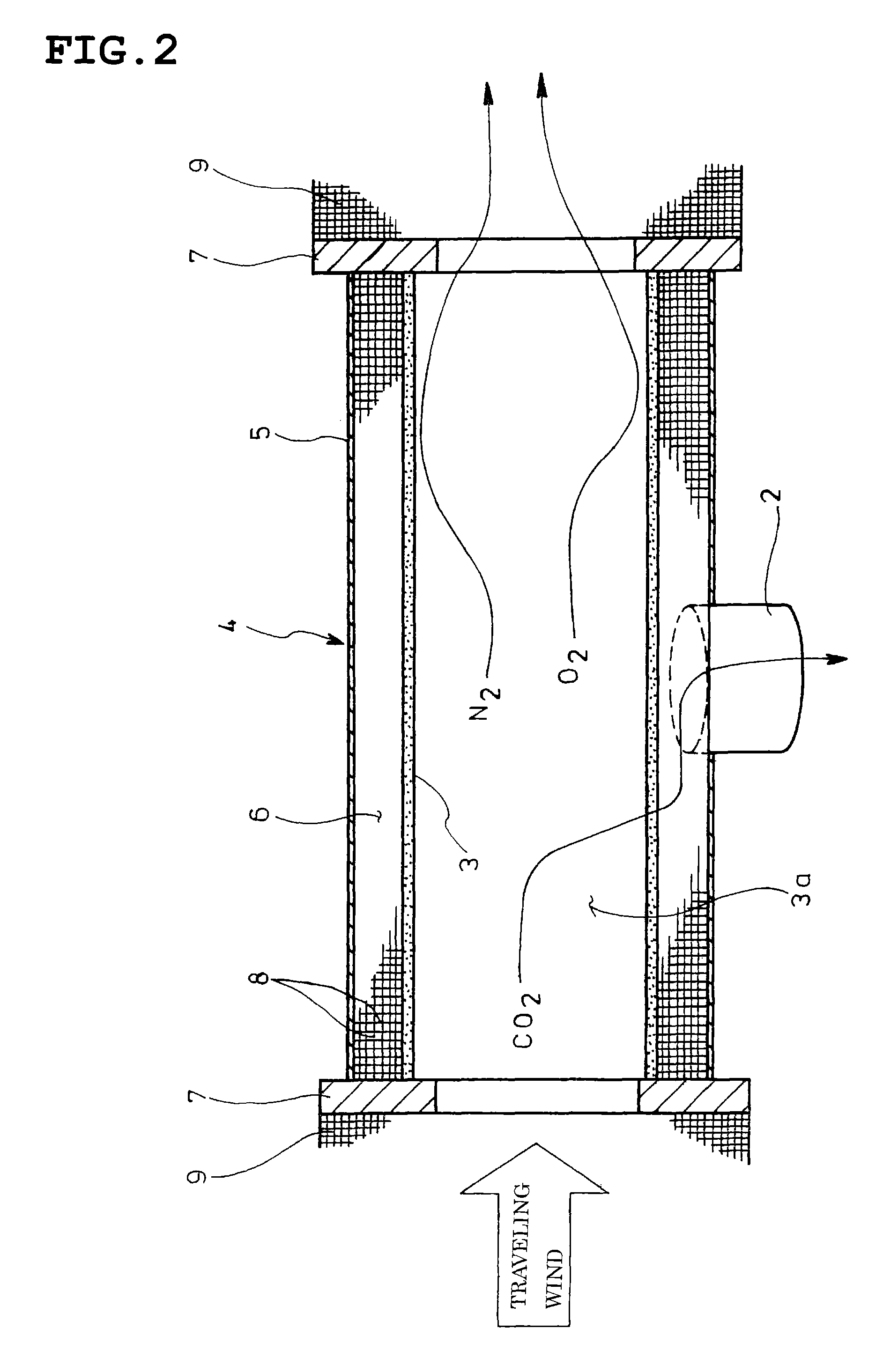
[0028]FIGS. 1 and 2 show an embodiment of the invention. In the embodiment illustrated, a breather 2 on a top of a tank body 1 is open to an atmospheric air through a carbon dioxide permeable membrane 3 such that an inert gas containing plenty of carbon dioxide permeated through the membrane 3 can be taken into the tank body 1 by a negative pressure due to reduction of the fuel F in the tank body 1. More specifically, the membrane 3 is cylindrically formed to secure an air flow path 3a centrally of the cylindrical membrane, and a carbon dioxide collecting chamber 4 is formed on an outer periphery of the cylindrical membrane 3 and is connected with the breather 2.

[0029]The chamber 4 is defined by a cylindrical outer shell 5 coaxially surrounding the cylindrical membrane 3 with a required distance and torus-shaped blocking plates 7 closing a space 6 between the outer shell 5 and the membrane 3 at lon...


PUM

PropertyMeasurementUnit
pressureaaaaaaaaaa
permeableaaaaaaaaaa
viscosityaaaaaaaaaa

Abstract

A breather 2 on a top of a tank body 1 is opened through a carbon dioxide permeable membrane 3 to an atmospheric air so as to take an inert gas containing plenty of carbon dioxide permeated through the membrane 3 into the tank body 1 by a negative pressure due to reduction of a fuel F in the tank body 1.

Description

TECHNICAL FIELD[0001]The present invention relates to a fuel tank for a vehicle.BACKGROUND ART[0002]In recent years, a bio-diesel fuel made from biological oils attracts attentions as one of countermeasures against global warming. Utilized are various fats such as colza oil in Europe, Pistacia chinensis and the like in China, soybean oil in North, Central and South America and oil palm, coconut palm and Jatropha curcas in Southeast Asia.[0003]There is concern that direct use of such fats, which have a feature of high viscosity among others, as they are as fuel for a diesel automobile would cause failure of an engine due to adhesion of deposits on a fuel pump. Thus, used is fatty acid methyl ester (abbreviated as FAME using initials) or the like with physical properties similar to those of diesel oil and obtained through conversion of the raw fats by removing glycerin therefrom in a chemical treatment such as methyl esterification.[0004]More specifically, the fats are added with meth...

Claims


Application Information

Patent Timeline
Patent Type & Authority Patents(United States)
IPC IPC(8): B01D53/22
CPCB60K2015/03243B60K15/035B01D53/22Y02C10/10B60K2015/03236F02M37/0076B01D2257/504Y02C20/40
Inventor UCHIDA, NOBORU
Owner HINO MOTORS LTD
Why Eureka
Try Eureka