Radar imaging apparatus, imaging method, and program thereof

a technology of radar and imaging apparatus, applied in direction finders, instruments, measurement devices, etc., can solve the problems of difficult to distinguish between human body temperature and an outside environment in a place, system using a camera faces an extreme fall in sensitivity, and system is expensive, so as to enhance the detection function

Inactive Publication Date: 2014-04-01
PANASONIC CORP
View PDF25 Cites 57 Cited by
  • Summary
  • Abstract
  • Description
  • Claims
  • Application Information

AI Technical Summary

Benefits of technology

[0055]The present invention can provide a radar imaging apparatus which can enhance a function of detecting a direction of a moving target.

Problems solved by technology

In addition to counter-terrorism measures spreading worldwide, human detection is the most important problem for nursing care for the elderly and rescue operations after a disaster.
However, there is a problem that a system using infrared ray has difficulty in distinguishing between human body temperature and an outside environment in a place where temperature is high.
Moreover, there is a problem that a system using a camera faces an extreme fall in sensitivity in an environment where light cannot be sufficiently captured at night or during bad weather.
However, there are many cases where imaging using radar requires many antennas or receivers in order to obtain sufficient data for estimating a shape.
However, imaging using the radar leads to enlarging or complicating the system with a result that the system is expensive.

Method used


Image

  • Radar imaging apparatus, imaging method, and program thereof
  • Radar imaging apparatus, imaging method, and program thereof
  • Radar imaging apparatus, imaging method, and program thereof

Examples


embodiment 1

(Modification of Embodiment 1)

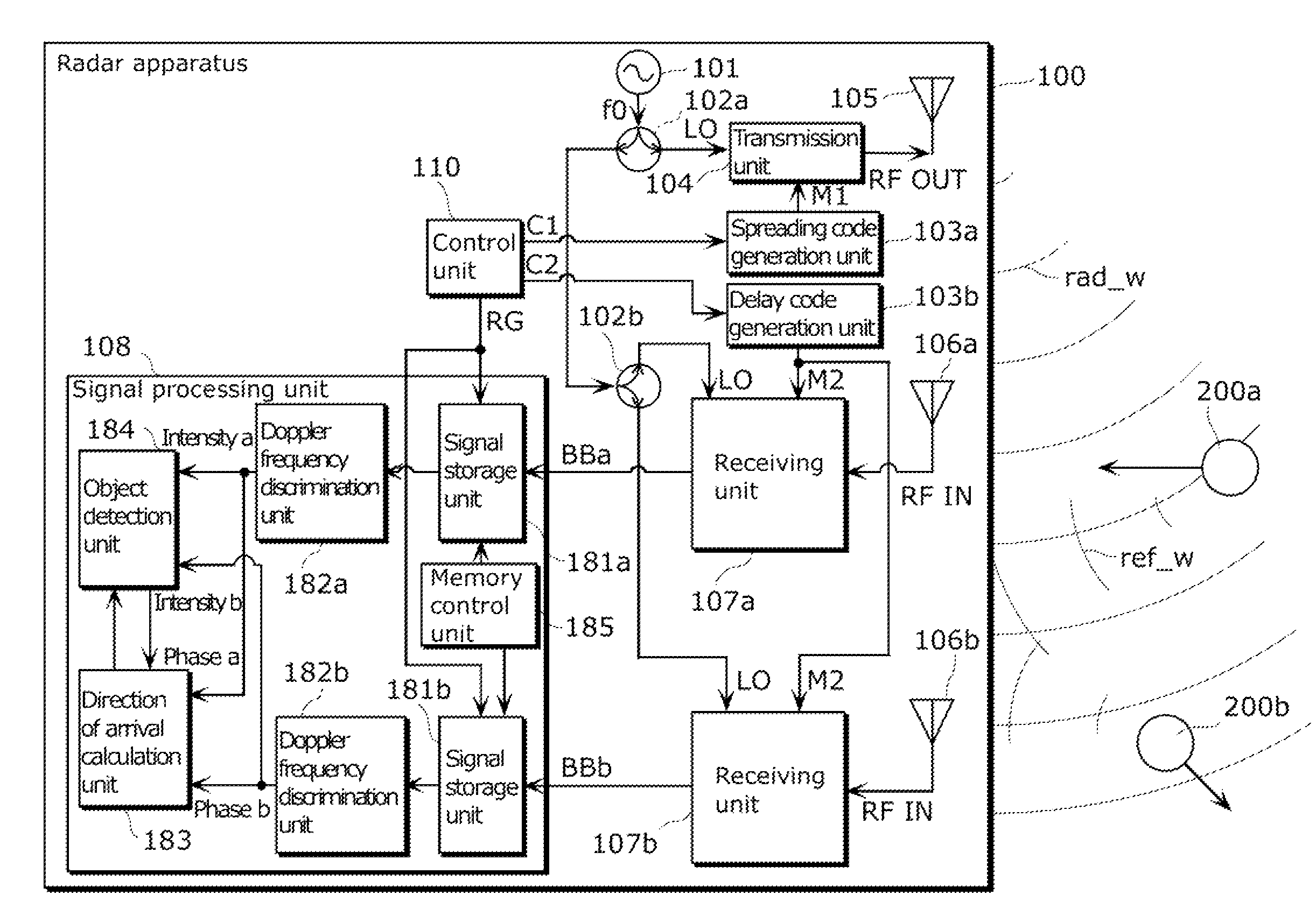
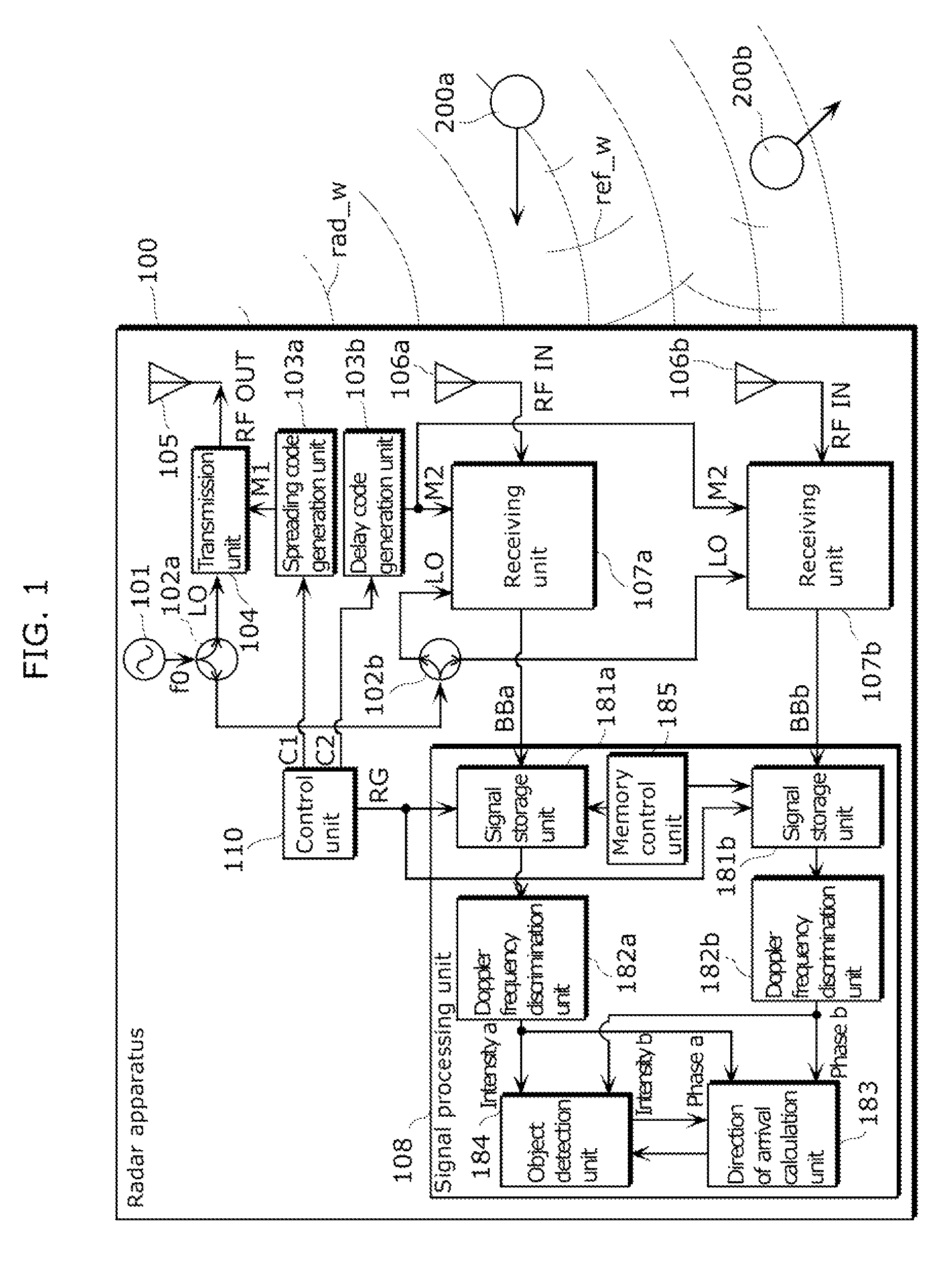
[0179]Moreover, in the Embodiment 1, the object detection unit 184 can discretely detect an existence position of a target by determining a range gate as a unit, and furthermore, the object detection unit 184 may calculate a detailed existence position within the range gate, which is more detailed than a length of the range gate RG=c / (2×CR) calculated by using a light velocity c with respect to a chip rate CR of the spreading code M1 and the delay code M2.

[0180]A radar apparatus according to the present modification is almost the same as the radar apparatus according to Embodiment 1, but the difference from Embodiment 1 is that the object detection unit 184 (i) identifies, from an intensity distribution of the Doppler frequencies with respect to a delay time for each of the Doppler frequencies detected by the Doppler frequency discrimination unit 182a and the Doppler frequency discrimination unit 182b, a peak intensity in which an intensity becomes maxi...

embodiment 2

[0193]Next, a radar apparatus according to Embodiment 2 will be described.

[0194]The radar apparatus according to the present embodiment is almost the same as the radar apparatus 100 according to Embodiment 1, but further includes a control unit configured to control (i) a first operation mode in which the delay code generation unit 103b repeats the scan processing M times and (ii) a second operation mode in which the delay code generation unit 103b repeatedly generates the same delay code, wherein the control unit is configured to determine, in the first operation mode, whether or not there is a Doppler frequency component having an intensity equal to or greater than a predetermined second threshold value, and switch to the second operation mode when it is determined that there is the Doppler frequency component having the intensity equal to or greater than the predetermined second threshold value, the intensity being detected by the Doppler frequency discrimination units 182a and 1...


PUM


Abstract

A radar imaging apparatus includes: (i) a delay code generation unit which repeats, for M scan periods, scan processing of generating, using a transmission code, N delay codes in a scan period for scanning N range gates having mutually different distances from the radar imaging apparatus; (ii) a signal storage unit which stores, in association with a range gate and a scan period, a baseband signal; (iii) a memory control unit which repeatedly writes, in the signal storage unit, for the M scan periods, N demodulated signals corresponding to a single scan period, and reads out a group of M demodulated signals corresponding to mutually different scan periods; (iv) a Doppler frequency discrimination unit which performs frequency analysis on demodulated signals having the same range gate; and (v) a direction of arrival calculation unit which estimates a direction of a target.

Description

CROSS REFERENCE TO RELATED APPLICATIONS[0001]This is a continuation application of PCT application No. PCT / JP2011 / 003657 filed on Jun. 27, 2011, designating the United States of America, which is based on claim priority of Japanese Patent Application No. 2010-178959 filed on Aug. 9, 2010. The entire disclosures of the above-identified application, including specification, drawings and claims are incorporated herein by reference in its entirety.TECHNICAL FIELD[0002]The present invention relates to a radar imaging apparatus and an imaging method of detecting a target object by radiating a transmission signal and by receiving reflected waves of the transmission signal reflected from the target object.BACKGROUND ART[0003]In recent years, there has been a growing demand for human body detection with the aim of offering security and safety in various social fields. In addition to counter-terrorism measures spreading worldwide, human detection is the most important problem for nursing care...

Claims


Application Information

Patent Timeline
Patent Type & Authority Patents(United States)
IPC IPC(8): G01S13/42G01S13/64
CPCG01S13/64G01S13/89G01S13/288G01S3/48G01S2007/2886G01S7/2886
Inventor FUKUDA, TAKESHIINOUE, KENICHISATO, TORUSAKAMOTO, TAKUYASAHO, KENSHI
Owner PANASONIC CORP
Why Eureka
Try Eureka