
Voltage regulator, voltage regulation method, and liquid crystal display device using the same

a voltage regulation method and voltage regulation technology, applied in the direction of electric digital data processing, instruments, computing, etc., can solve the problems of noise generation and adverse effects on user experience of liquid crystal display devices

Active Publication Date: 2014-04-01
INNOLUX CORP
View PDF1 Cites 0 Cited by
  • Summary
  • Abstract
  • Description
  • Claims
  • Application Information

AI Technical Summary

Benefits of technology

The patent describes a method to reduce noise in liquid crystal displays by inverting the voltage in a periodic way to change the electric field between the substrates. While this helps prevent polarization of the liquid crystals, it also generates noise at a specific frequency. The technical effect of this patent is to reduce the impact of noise on the user experience of liquid crystal display devices.

Problems solved by technology

However, noise is generated by the oscillation of the liquid crystals in the periodical changing electric field, and the noise is focused at a specific frequency.
If the noise frequency is in the audible range, a user's experience of the liquid crystal display device can be adversely affected.

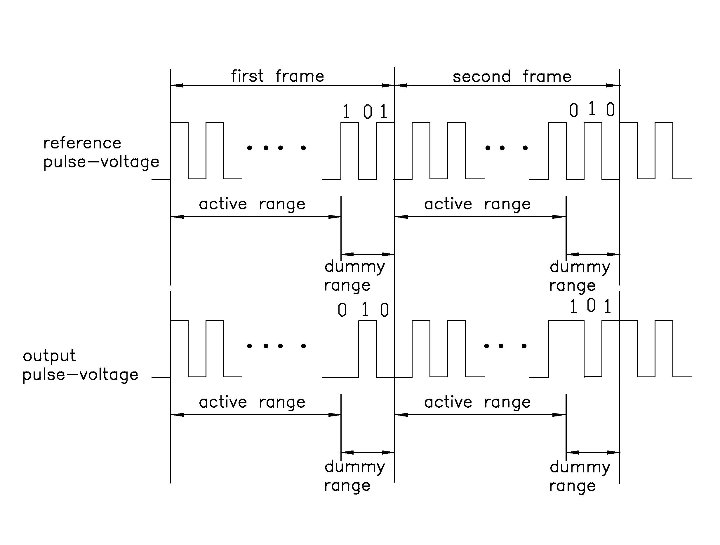
Method used


Image

  • Voltage regulator, voltage regulation method, and liquid crystal display device using the same
  • Voltage regulator, voltage regulation method, and liquid crystal display device using the same
  • Voltage regulator, voltage regulation method, and liquid crystal display device using the same

Examples


first embodiment

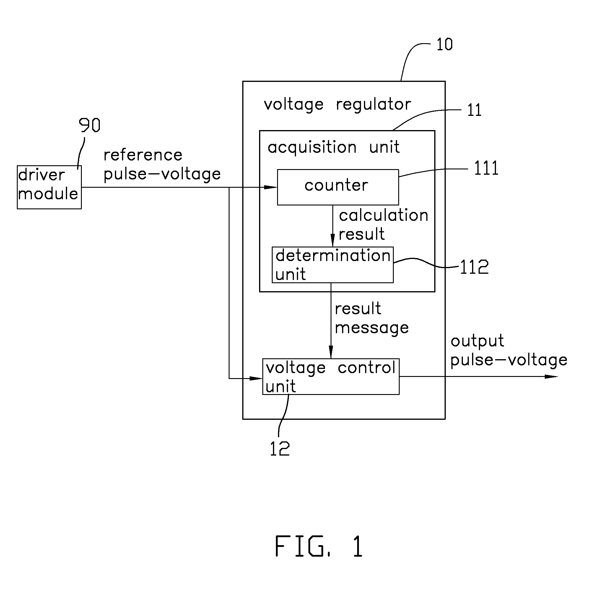
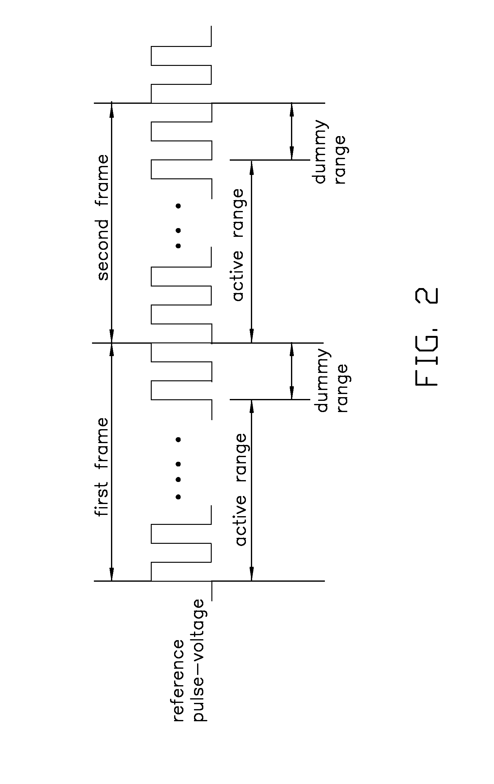
[0016]Referring to FIG. 1 and FIG. 2, a voltage regulator 10 adapted to regulate a reference pulse-voltage generated by a driver module 90 is shown. In this example, the reference pulse-voltage consists of a periodical sequence of alternating positive and negative pulses.

[0017]The driver module 90 is adapted to drive the liquid crystals of an associated liquid crystal display device to display images corresponding to a sequence of frames. The frames include a first frame and a second frame next to the first frame, as illustrated in FIG. 2. The reference pulse-voltage includes active pulses and dummy pulses in any one frame. A series of continuous active pulses in any one frame forms an active range applying to a display area of the liquid crystal display device, and a series of continuous dummy pulses in the same frame forms a dummy range applying to a non-display area of the liquid crystal display device. That is, the voltage pulses, comprising positive pulses and negative pulses, ...

second embodiment

[0028]Referring to FIGS. 1 and 5, a voltage regulation method employing the second voltage regulator is described as follows.

[0029]In step S71′, the acquisition unit 11 receives a pulse of the reference pulse-voltage generated by the driver module 90.

[0030]In step S72′, the counter 111 updates a calculation result by adding one to the previous calculation result, and transmits the calculation result to the determination unit 112. At the time the voltage regulation method is begun, the initial value of the calculation result is preset to zero.

[0031]In step S73′, the determination unit 112 determines whether the calculation result is equal to the set value. When the calculation result is equal to the set value, step S75′ is implemented. When the calculation result is other than the set value, step S74′ is implemented. For instance, the driver module 90 drives the liquid crystals to display a frame with 640*480 dpi; and in each frame, the reference pulse-voltage includes 307200 active ...


PUM


Abstract

A voltage regulator for controlling a reference pulse-voltage comprising a sequence of positive-negative pulses which defines an active range and a dummy range is disclosed. The voltage regulator includes an acquisition unit adapted to receive each pulse of the reference pulse-voltage and determine whether an alteration of the pulse is needed according to a predetermined calculation, and generate a result message when it is determined that an alteration of the voltage pulse is needed, and a voltage control unit adapted to generate an output pulse-voltage corresponding to the reference pulse-voltage. When no result message is generated, the voltage control unit is configured to output an output pulse having the same polarity as that of the received pulse of the reference pulse-voltage, and when the result message is generated, the voltage control unit is configured to output an output pulse having an opposite polarity to that of the received pulse.

Description

BACKGROUND[0001]1. Technical Field[0002]The present disclosure generally relates to a voltage regulator and a method providing dispersion of noise energy in a liquid crystal display device, and a liquid crystal display device using the voltage regulator.[0003]2. Description of Related Art[0004]A commonly used liquid crystal display device is provided with a driver module to generate drain and common voltages applied to an upper glass substrate and a lower glass substrate of the liquid crystal display device, respectively. An electric field generated between the substrates aligns liquid crystals toward predetermined directions to generate a display.[0005]A commonly used line inversion method periodically changes the polarity of the common voltage such that the direction of the electric field between the substrates is changed accordingly. Thus, periodical force in different directions acts on the liquid crystals to avoid polarization thereof. However, noise is generated by the oscilla...

Claims


Application Information

Patent Timeline
Patent Type & Authority Patents(United States)
IPC IPC(8): G06F3/038
CPCG09G3/3614G09G3/3655G09G2310/08
Inventor TSAI, JENG-LUNG
Owner INNOLUX CORP
Learn More