

Permanent magnetism type excitation method in use for electromagnetic flowmeter
A technology of electromagnetic flowmeter and excitation method, which is applied in the application of electromagnetic flowmeter to detect fluid flow, volume/mass flow generated by electromagnetic effect, etc. problem, to achieve the effect of simple structure, avoiding interference and improving response speed
- Summary
- Abstract
- Description
- Claims
- Application Information
AI Technical Summary
Problems solved by technology
Method used
Image

Examples
Embodiment Construction
[0030] The present invention will be further described below in conjunction with the accompanying drawings and embodiments.
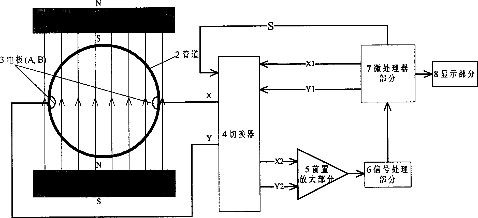
[0031] exist figure 1 In the implementation form of scheme 1 shown, two pieces of permanent magnets 1 are facing to the two sides of the pipeline 2, and the polarities of the two pieces of permanent magnets are arranged in the same direction. The pipe 2 is internally provided with an insulating layer, or a measuring tube itself formed of insulating material. The conductive fluid flows through the measuring tube 2 . An electrode 3 is installed on the inner wall of the measuring tube 2 perpendicular to the diameter direction of the magnetic field, and the electrode 3 is insulated from the measuring tube 2 .
[0032] The input control signal S terminal of the switcher 4 is connected with an output terminal of the microprocessor part 7, the input voltage signal terminal X1, Y1 of the switcher 4 is connected with two output terminals of the microprocessor ...
PUM
 Abstract
Description
Claims
Application Information