Electroacoustic transducer

An electroacoustic transducer and vibration system technology, applied in the field of electroacoustics, can solve the problems of increasing the difficulty of use and insufficient flexibility of the centering support

Active Publication Date: 2012-12-05
GOERTEK INC
View PDF3 Cites 13 Cited by
  • Summary
  • Abstract
  • Description
  • Claims
  • Application Information

AI Technical Summary

Problems solved by technology

The process of electrically connecting the pad/shrapnel structure to the external circuit is easy, and the strut can effectively prevent the polarization during the vibration of the v

Method used


Image

  • Electroacoustic transducer
  • Electroacoustic transducer
  • Electroacoustic transducer

Examples


Embodiment Construction

[0025] The present invention will be further described in detail below in conjunction with the accompanying drawings and specific embodiments.

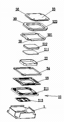
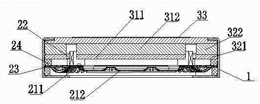
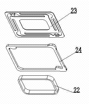
[0026] Such as figure 1 and figure 2 As shown, the electro-acoustic transducer includes a vibration system, a magnetic circuit system, and a casing 1 for accommodating the fixed vibration system and the magnetic circuit system. The vibration system includes a diaphragm 21 and a voice coil 22 combined on one side of the diaphragm 21, wherein the diaphragm 21 includes a diaphragm body part 211 and a composite layer 212 combined at the center of the diaphragm body part 211, the composite layer 212 can enhance the vibration High-frequency properties of the membrane. The electric connection assembly for electrically connecting the internal circuit and the external circuit of the electro-acoustic transducer of the present invention includes a damper 23 and a hard ring-shaped reinforcing part 24 combined with the edge of the damper 23 . ...


PUM


Abstract

The invention discloses an electroacoustic transducer. The electroacoustic transducer comprises an oscillating system, a magnetic circuit system, and a shell for accommodating and fixing the oscillating system and the magnetic circuit system, wherein the oscillating system comprises an oscillating diaphragm and a voice coil which is jointed on one side of the oscillating diaphragm; the shell has a metal structure; the electroacoustic transducer further comprises a centering disk which is jointed with the oscillating system; a hard reinforcing part is arranged on the edge of the centering disk; a welding pad and a circuit for electrically connecting the welding pad and the centering disk are arranged on the reinforcing part; the voice coil comprises a voice coil lead; and the voice coil lead is electrically connected with the centering disk. By adopting the structure, the oscillating diaphragm can be protected from polarization; and an operating process for electrically connecting with an external circuit is simple.

Description

technical field [0001] The invention relates to the field of electroacoustics, in particular to an electroacoustic transducer. Background technique [0002] In the prior art, the electro-acoustic transducer includes a vibration system, a magnetic circuit system, and a housing that accommodates and fixes the vibration system and the magnetic circuit system; usually, the internal circuit of the electro-acoustic transducer communicates with the external circuit through an electrical connection assembly . The vibration system includes a diaphragm and a voice coil combined on the lower side of the diaphragm. The voice coil includes a voice coil lead wire, and the voice coil lead wire is electrically connected to the electrical connection component, and finally realizes the electrical connection with the terminal product. [0003] The electrical connection components in the prior art are mainly pad / shrapnel structures, or centering strut structures. The process of electrically c...

Claims


Application Information

Patent Timeline
IPC IPC(8): H04R9/06H04R9/02
Inventor 王泽
Owner GOERTEK INC
Why Eureka
Try Eureka