Vortex-enhanced filtration devices

a technology of filtration device and filtration membrane, which is applied in the direction of filtration separation, membrane, separation process, etc., can solve the problems of difficult manufacturing of hollow fiber cartridges, toxic to patients, and many of the chemicals needed in manufacture, so as to prevent concentration polarization and enhance mass transfer across the dialysis membrane

Active Publication Date: 2007-05-22
MCLAUGHLIN TRUSTEE OF THE JENNIFER MCLAUGHLIN TRUST JENNIFER K
View PDF20 Cites 15 Cited by
  • Summary
  • Abstract
  • Description
  • Claims
  • Application Information

AI Technical Summary

Benefits of technology

[0013]In a preferred embodiment, the present invention relates to a device for hemodialysis. The device comprises a cylindrical housing having a housing wall; a first cylindrical rotor having a first wall comprising a dialysis membrane, wherein the first cylindrical rotor is disposed coaxially within the housing and adapted to rotate therein, such that a first coaxial gap exists between the dialysis membrane and the housing wall. There is also included a second cylindrical rotor having a second wall, wherein the second cylindrical rotor is disposed coaxially within the first cylindrical rotor and adapted to rotate therein, such that a second coaxial gap exists between the first and second walls. The device also includes a first inlet port in the housing wall for conducing blood into the first coaxial gap and a first outlet port in the housing wall for conducting dialyzed blood out of the first coaxial gap. A second inlet port is included in the housing for conducting dialysis fluid into the second coaxial gap and a second outlet port is included for conducing dialysate out of the second coaxial gap. The device also comprises first and second rotational drive means for rotating the first and second cylindrical rotors respectively within the cylindrical housing. Consequently, when the first and second rotors are spun, Taylor vortices may be created in the first and second coaxial gaps, thereby enhancing mass transfer across the dialysis membrane and preventing concentration polarization on both sides of the membrane.
[0016]In another preferred embodiment, the present invention relates to a device to facilitate mass transfer. The device comprises a housing having a housing wall; a first rotor having a first wall comprising a filtration membrane, wherein the first rotor is disposed within the housing and adapted to rotate therein, such that a first gap exists between the filtration membrane and the housing wall. There is also included a second rotor having a second wall, wherein the second rotor is disposed within the first rotor and adapted to rotate therein, such that a second gap exists between the first and second walls. The device also includes a first inlet port in the housing wall for conducing a first fluid into the first gap and a first outlet port in the housing wall for conducting filtered first fluid out of the first gap. The device also comprises first and second rotational drive means for rotating the first and second rotors respectively within the housing. Consequently, when the first and second rotors are spun, Taylor vortices may be created in the first and second gaps, thereby enhancing mass transfer across the filtration membrane and preventing concentration polarization on both sides of the membrane.
[0017]In another preferred embodiment, the present invention relates to a device to facilitate heat transfer. The device comprises a housing having a housing wall; a first rotor having a first wall comprising a filtration membrane, wherein the first rotor is disposed within the housing and adapted to rotate therein, such that a first gap exists between the filtration membrane and the housing wall. There is also included a second rotor having a second wall, wherein the second rotor is disposed within the first rotor and adapted to rotate therein, such that a second gap exists between the first and second walls. The device also includes a first inlet port in the housing wall for conducing a first fluid into the first gap and a first outlet port in the housing wall for conducting filtered first fluid out of the first gap. The device also comprises first and second rotational drive means for rotating the first and second rotors respectively within the housing. Consequently, when the first and second rotors are spun, Taylor vortices may be created in the first and second gaps, thereby enhancing mass transfer across the filtration membrane and preventing concentration polarization on both sides of the membrane.

Problems solved by technology

While hollow fiber technology provides a relatively safe and cost effective means for dialysis, problems remain.
Manufacturing hollow fiber cartridges is challenging.
Many of the chemicals needed in manufacture are toxic to the patient.
Cuprophane is the most common membrane material for hollow fiber manufacture, but it has biocompatibility issues, and relatively low permeability performance.
There are superior membrane materials available in flat sheet, but these materials are challenging to form into hollow fibers.
One of the most limiting problems in any type of filtration process, including dialysis, is filter clogging, scientifically described as “concentration polarization.” As a result of the selective permeability properties of the membrane, the filtered material that cannot pass through the membrane becomes concentrated on the surface of the membrane.
Consequently, filtrate flux is reduced and filtration performance diminishes.
Fischel also describes variations in the width of the gap between a rotary spinner and a cylindrical housing, but does not teach variation in this width about a circumferential cross-section.
Taylor-Couette filtration devices generate strong vorticity as a result of centrifugal flow instability (“Taylor instability”), which serves to mix the filtered material concentrated along the filter back into the fluid to be processed.
It has been observed that membrane fouling due to concentration polarization is very slow compared to dead-end or tangential filtration.
Further, these separators only had to operate for relatively short periods of time (e.g., about 45 minutes).
The use of Taylor vortices does not alleviate all problems with filtration however.
Another common problem with the use of such rotating filtration devices is concentration polarization on the inner side of the filter membrane.
While centrifugal flow instability circulates the fluid between inner and outer members, the rotating inner member does not prevent concentration polarization near the walls of its interior.

Method used


Image

  • Vortex-enhanced filtration devices
  • Vortex-enhanced filtration devices
  • Vortex-enhanced filtration devices

Examples


Embodiment Construction

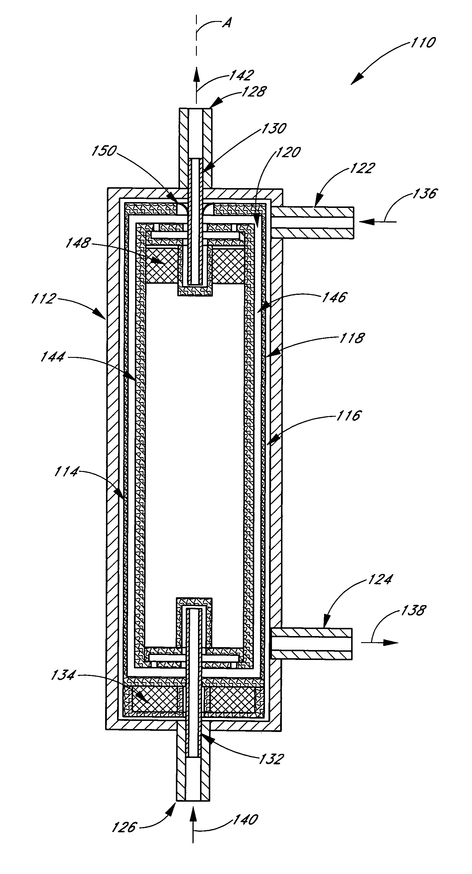
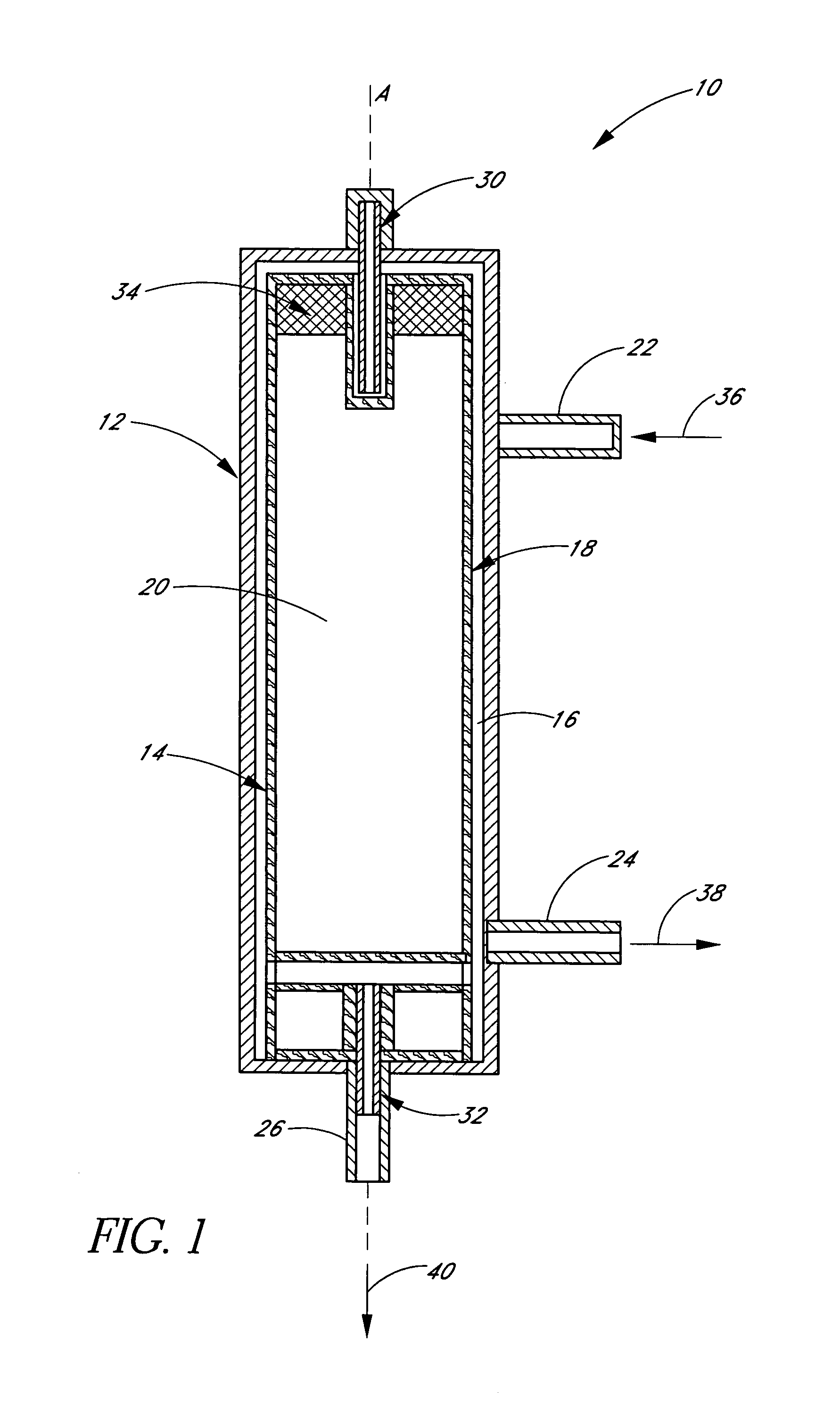
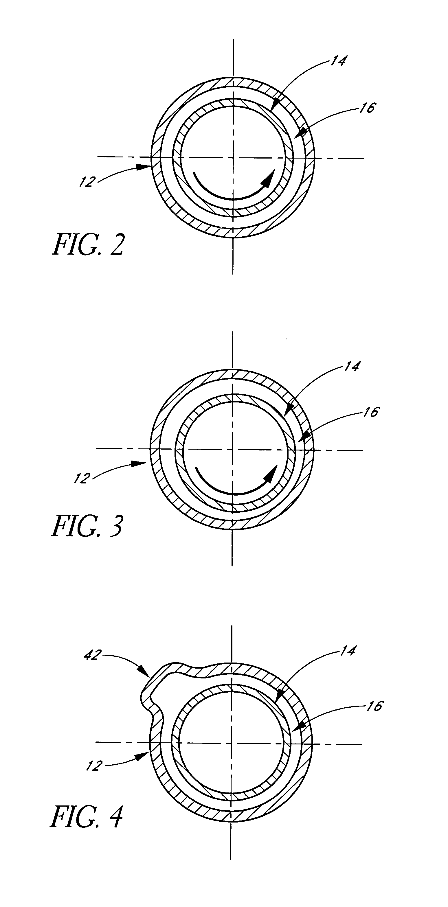
[0031]It is well known that Taylor vortices, otherwise referred to herein as Taylor vorticity, can increase the mass transfer through a filter by one or two orders of magnitude. This is useful where it is desirable to remove a component of a fluid by size separation from a feed fluid. For example, Taylor vorticity is useful in removing plasma from blood. Here the separation mechanism is accomplished by the pore size of the filter.

[0032]In other separation processes the components of the feed fluid are removed by following a concentration gradient. An example of this is in dialysis and, in particular, blood dialysis. Here, urea and other low molecular weight waste by-products are removed from blood by placing blood on one side of a membrane and a fluid with low concentrations of urea and other waste by-products on the other side of the membrane. The urea and other waste by-products follow the concentration gradient and move through the membrane from the blood to the dialysis fluid. A...


PUM

PropertyMeasurementUnit
massaaaaaaaaaa
diameteraaaaaaaaaa
diameteraaaaaaaaaa

Abstract

Preferred aspects of the present invention relate to a device for filtration comprising at least one rotor configured to create Taylor vortices on at least one side of a filtration membrane, thereby providing substantially enhanced mass or heat transfer across the membrane.

Description

RELATED APPLICATIONS[0001]This application claims priority under 35 U.S.C. §119(e) to U.S. Provisional Application No. 60 / 453,620, filed on Mar. 10, 2003.BACKGROUND OF THE INVENTION[0002]1. Field of the Invention[0003]Preferred aspects of the present invention relate to a device that creates Taylor vortices on at least one side of a filter, thereby improving mass transfer and minimizing concentration polarization. Preferred embodiments of the present invention are particularly useful in dialysis of blood from patients with kidney disease. In other embodiments, the present invention can be used in areas of heat and mass transfer.[0004]2. Description of the Related Art[0005]Traditionally, dialysis is the maintenance therapy used to treat kidney disease. There are two common approaches. One is peritoneal dialysis, where the process is done internally to the patient, in the patient's pericardium. Peritoneal dialysis uses the patient's abdominal lining as a blood filter. The abdominal ca...

Claims


Application Information

Patent Timeline
Patent Type & Authority Patents(United States)
IPC IPC(8): B01D63/16B01D61/24B01D63/06B01D61/00A61M1/16A61M1/26
CPCB01D61/243B01D61/28B01D63/065B01D63/16A61M1/265A61M1/16B01D2315/02A61M2205/3365A61M2205/50A61M1/3623
Inventor MCLAUGHLIN, JENNIFER K.SCHOENDORFER, DON
Owner MCLAUGHLIN TRUSTEE OF THE JENNIFER MCLAUGHLIN TRUST JENNIFER K
Why Eureka
Try Eureka