Embeddable device for passing conduits through a constructional component

a technology of construction components and embeddable devices, which is applied in the direction of mechanical equipment, walls, flooring, etc., can solve the problems of insufficient stability, inability to arrange cast-in devices in space-optimizing manners, and presenting problems, and achieve stable connection of two housing parts, cost-effective effect, and easy assembly

Active Publication Date: 2014-04-08
HILTI AG
View PDF5 Cites 18 Cited by
  • Summary
  • Abstract
  • Description
  • Claims
  • Application Information

AI Technical Summary

Benefits of technology

[0012]By providing a connection element spaced from the attachment flange, there is provided, upon connection of two devices for forming a cast-in system, an additional attachment point for both devices and which, in connection with two or three attachment points on the attachment flanges, insures a stable and space-saving arrangement of the cast-in system. Such cast-in system is capable to withstand forces acting thereon even at a small number of attachment points on the attachment flange before casting of the constructional component. Of course, the inventive device can be used as a single leadthrough.
[0030]Advantageously, the embeddable device is formed of a plastic material, in particular, by an injection-molding process. This insures a cost-effective manufacturing of the inventive embeddable device. With the plastic material, the connection device is also produced with low costs. This is particularly advantageous in mass production in which the embeddable device according to the present invention is produced.

Problems solved by technology

The open leadthroughs present a danger that, e.g., in case of fire, they would facilitate propagation of the fire.
The drawback of the devices described above consists in that they are designed for a single leadthrough for passing a conduit.
Because of a limited space and because of the shape of the devices, in particular of their attachment flanges, the cast-in devices cannot be arranged in a space-optimizing manner.
With narrow space ratios, this presents a problem.
The drawback of the device of DE 24 11 521 A1 consists in that with two devices arranged next to each other, in particular with vertically extending leadthroughs, an attachment point provided by the connection device, does not have an adequate stability and does not provide protection against displacement of the devices.

Method used


Image

  • Embeddable device for passing conduits through a constructional component
  • Embeddable device for passing conduits through a constructional component
  • Embeddable device for passing conduits through a constructional component

Examples


Embodiment Construction

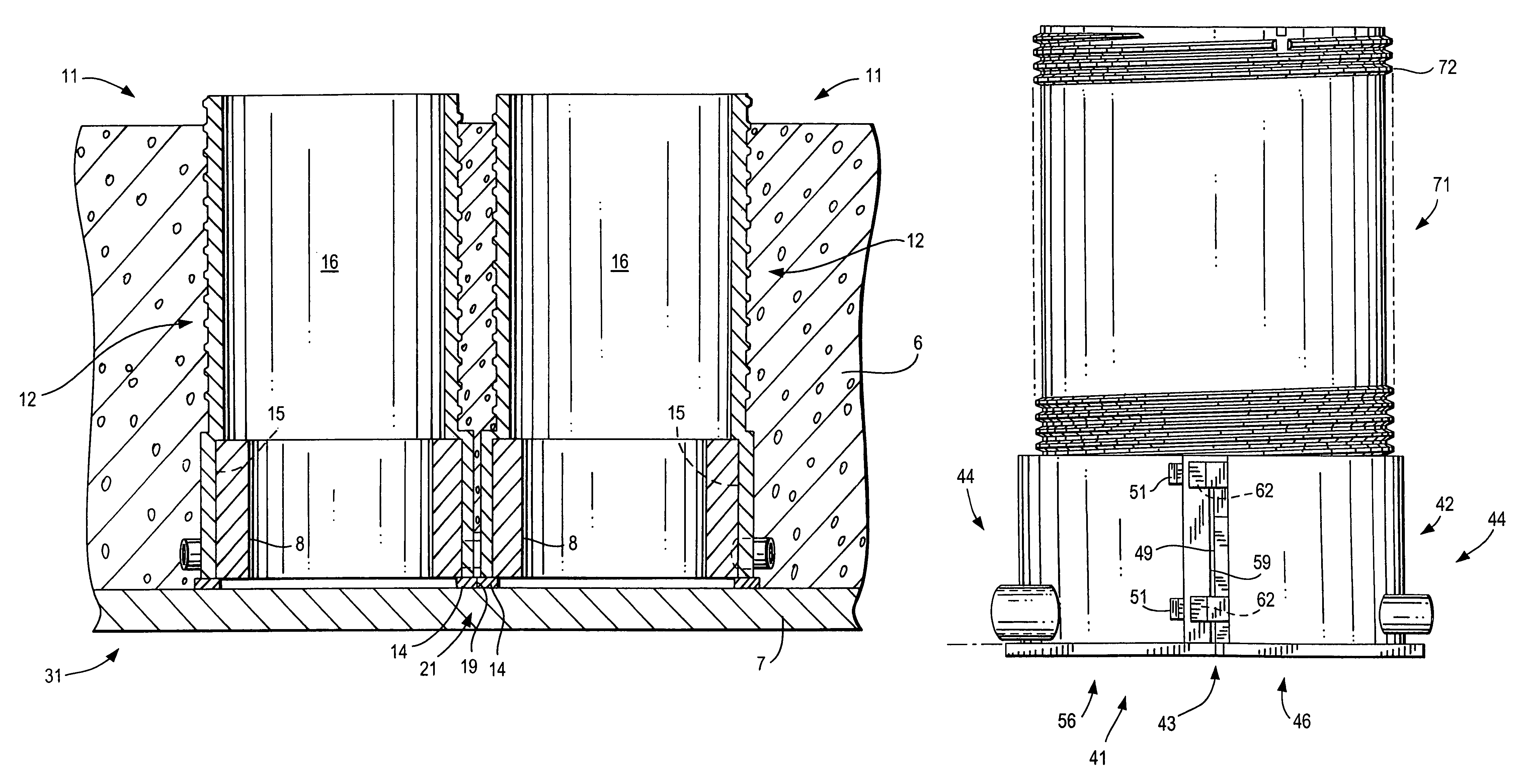
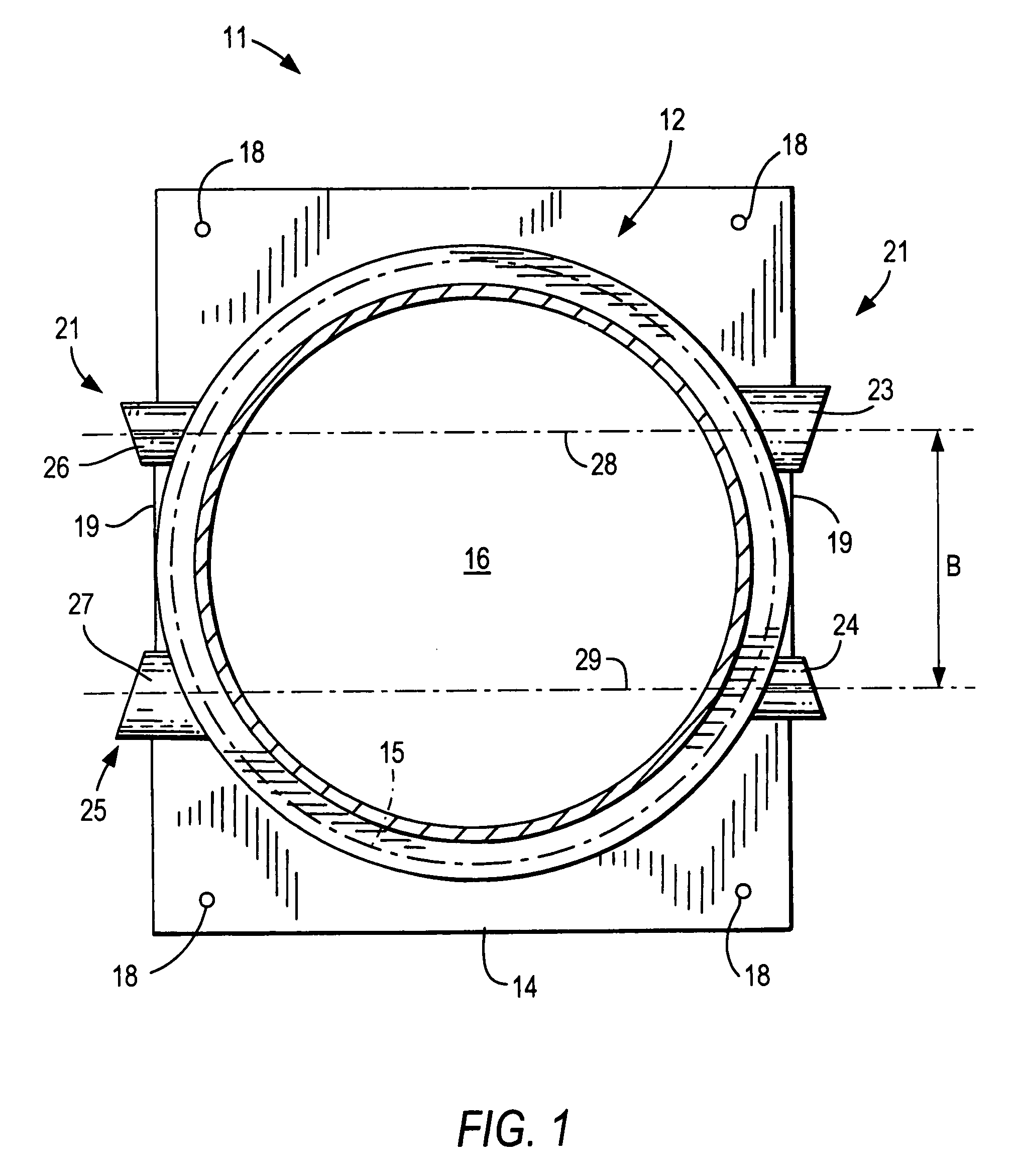
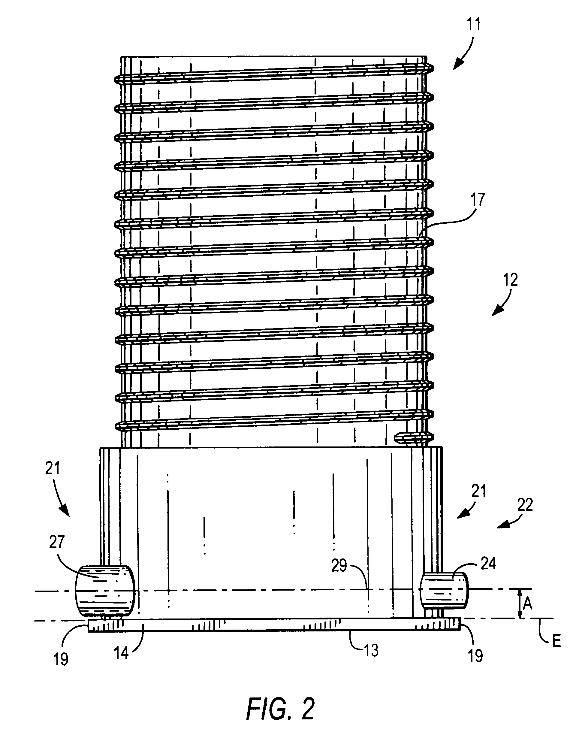
[0038]An embeddable device 11 according to the present invention for passing of conduits through constructional components, which is shown in FIGS. 1-2, includes a tubular housing 12 at an end 13 of which, there is provided an attachment flange 14 for a temporary preliminary mounting of the device 11 on a formwork of a subsequently cast constructional component. The attachment flange 14 projects in a direction transverse to the longitudinal extent of the tubular housing 12, beyond the tubular housing 12. The tubular housing 12 further includes a receptacle 15 for isolation means and which surrounds, at least regionwise, a through-opening 16 extending in the axial direction of the housing 12. The attachment flange 14 has a rectangular base surface in the corner regions of which, there are provided, respectively, holes 18 for nails, screws and the like for securing the device 11 on the formwork. For an improved anchoring of the device 11 in the cast constructional component, the housi...


PUM


Abstract

An embeddable device (11, 41) for passing conduits through a constructional component (6), includes a tubular housing (12, 42) having an attachment flange (14) provided at one of its ends for temporary securing the device on a formwork (7) of the subsequently cast constructional component (6), and a receptacle (15) for isolation means (8) and which surrounds, at least regionwise, an axially extending through-opening (16). A connection device (21, 44) connects a plurality of embeddable devices (11) with each other and includes at least one connection element (23, 24, 26, 27) provided on the housing (12) and extending parallel to a plane (E) defined by the attachment flange (14) at a distance from the plane (E).

Description

BACKGROUND OF THE INVENTION[0001]1. Field of the Invention[0002]The present invention relates to an embeddable device for passing conduits through a constructional component and including a tubular housing having an attachment flange provided at one of its ends for temporary securing the device on a formwork of the subsequently cast constructional component and a receptacle for isolation means and which surrounds, at least regionwise, an axially extending through-opening, and a connection device for connecting a plurality of embeddable devices with each other.[0003]2. Description of the Prior Art[0004]When designing and building buildings, on many occasions, there are provided, in walls and ceilings, leadthroughs for conduits such as pipes, cables and the like, through which only in a later constructional phase, e.g., in an expansion phase, conduits are passed. In this way, it is prevented that pipes, cables, or the like suffer any damage in earlier constructional phases. E.g., in o...

Claims


Application Information

Patent Timeline
Patent Type & Authority Patents(United States)
IPC IPC(8): E04F17/08
CPCE04F2290/02E04G15/061F16L5/10E04F17/08E04F2203/04F16L5/04F16L5/14
Inventor FISCHER, MARCOMONDEN, THOMAS
Owner HILTI AG
Why Eureka
Try Eureka