Grating-based tunable filter

A technology of optical filters and gratings, applied in diffraction gratings, instruments, optics, etc., can solve problems such as increasing dispersion angles

Active Publication Date: 2013-09-11
奥托莱克斯公司
View PDF7 Cites 15 Cited by
  • Summary
  • Abstract
  • Description
  • Claims
  • Application Information

AI Technical Summary

Problems solved by technology

This greatly increases the total dispersion angle, resulting in highly adjacent channel separation

Method used


Image

  • Grating-based tunable filter
  • Grating-based tunable filter
  • Grating-based tunable filter

Examples


Embodiment Construction

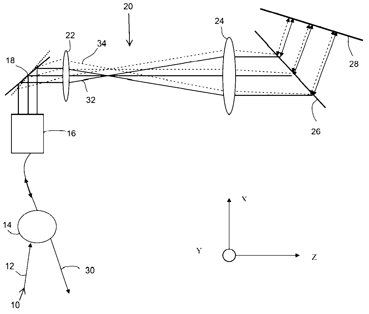
[0016] figure 1 It is a schematic diagram of an embodiment of the present invention. An input beam 10 comprising a spectrum of wavelengths is directed into an input fiber 12 of a circulator 14 . An input / output collimator 16 collimates the beam. The collimated beam hits a flat mirror 18 mounted on the rotary actuator. Such actuators are well known in the art. To achieve high spectral resolution, the beam needs to be expanded to a larger diameter to cover more reticles on the grating. Therefore, after the beam 10 is reflected by the plane mirror 18, it is amplified by the beam expander 20, and the beam expander 20 includes magnifying mirrors 22 and 24, both of which are positive lenses in this solution. The beam 10 is then transmitted to and through a transmission diffraction grating 26 . The different wavelengths of the transmitted beam are deflected to different angles by the diffraction grating. These wavelengths are transmitted to the flat mirror 28 and are reflected....


PUM


Abstract

In a grating-based tunable filter, an input beam that includes multiple wavelengths is directed into an input fiber of a circulator. The beam is collimated and then is reflected by a rotationally actuated mirror. The beam is then magnified and propagates onto and through a transmission diffraction grating which causes the different wavelengths of the transmitted beam to deflect into different angles. The wavelengths propagate onto and are reflected by a mirror and only a small portion of the wavelength spectrum of the transmitted beam will be reflected back along the incoming path and then propagated to the output fiber

Description

[0001] Cross reference to related applications [0002] This application claims priority to US Provisional Patent Application No. 13 / 441,899, entitled "A Grating-Based Tunable Filter," filed April 8, 2012, which is incorporated herein by reference. technical field [0003] The present invention relates to reconfigurable optical networks and spectrometer scan engines, and more particularly to tunable filters usable in the networks and engines. Background technique [0004] Various types of tunable optical filters are known in the art. Commonly used filters include rotating or tilting thin film bandpass optical filters, linear variable thin film filters, electrically controlled, thermally controlled or acoustically controlled wavelength tunable etalons, and thin film filter structures with thermally sensitive cavity layers located between reflective layers. [0005] US Patent No. 7,899,330, entitled "Compact High Resolution Tunable Optical Filter Using Light Diffractive Eleme...

Claims


Application Information

Patent Timeline
Patent Type & Authority Applications(China)
IPC IPC(8): G02B27/44G02B26/08
CPCG01J3/18G02B5/18G02B26/0816G02B26/105H04J14/02
Inventor 谢永杰
Owner 奥托莱克斯公司
Why Eureka
Try Eureka