Gas sensing using ultrasound

a technology of gas sensing and ultrasound, applied in the direction of instruments, chemical methods analysis, fluid analysis using sonic/ultrasonic/infrasonic waves, etc., can solve the problems of large problems, expensive and bulky systems, and difficult implementation, and achieve the effect of reducing the cost of using a single frequency and a huge problem

Active Publication Date: 2014-04-08
KONINKLJIJKE PHILIPS NV
View PDF10 Cites 43 Cited by
  • Summary
  • Abstract
  • Description
  • Claims
  • Application Information

AI Technical Summary

Benefits of technology

[0021]The use of a multi-frequency cMUT device for gas analysis makes it possible to perform a spectral study with a single, inexpensive and small device.
[0025]As the present inventors have observed, small sized on-chip ultra-sound transducers cannot be used for capnography measurements because of the required large dimensions of the ultrasound chamber to avoid turbulences and consequentially the long propagation length.
[0028]When adapting this airway system for an ultrasound based capnography sensor the signal becomes unstable, and extensive averaging is required. This in turn will slow down response time of the device, where from a diagnostic point of view it is required to have a relatively fast response.
[0072]In accordance with these, and other, aspects of the present invention, use of an all silicon ultrasound transducer, on-chip, allows the problems of bandwidth, power consumption, cost and weight to be overcome. Moreover, the cMUT technology is CMOS (complementary metal oxide semiconductor)-compatible, so that it can be integrated with the electronics for signal generation and data reduction. For example, it is easy to integrate a pressure sensor. Also, flexibility is gained in that the low-cost chip may be regarded as disposable.

Problems solved by technology

The multi-transducer solution is hard to implement as it results in a costly and bulky system when using standard transducers.
Although, as observed by the present inventors, it has been proposed to analyze gas concentrations using ultrasound, using a single frequency entails a huge problem: at one single frequency one can only measure one Time-Of-Flight (TOF) and one absorption coefficient.

Method used


Image

  • Gas sensing using ultrasound
  • Gas sensing using ultrasound
  • Gas sensing using ultrasound

Examples


Embodiment Construction

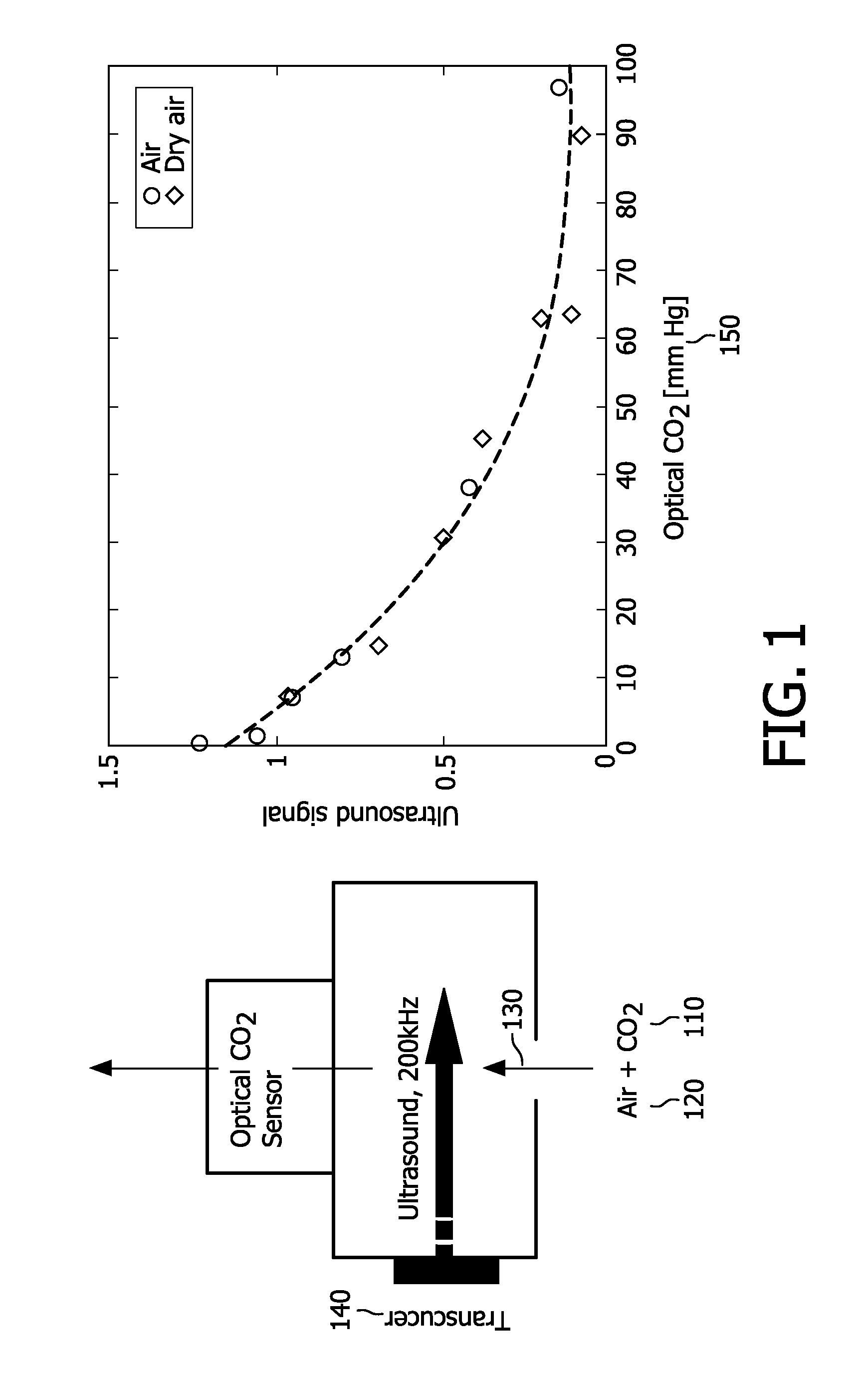
[0088]FIG. 1 depicts a conceptual and graphical comparison between optical and ultrasound approaches to capnography, in accordance with the present invention.

[0089]Carbon dioxide 110 absorbs IR (infrared) light of a specific wavelength, 4.3 nm. Because the amount of light absorbed is proportional to the concentration of the absorbing molecules, the CO2 concentration is determinable by comparing the measured absorbance with the absorbance of a known standard. The concentration is expressed as a partial pressure (of CO2) in mmHg.

[0090]In the ultrasound context, a gas, in particular CO2, has a characteristic absorption spectrum. It is noted that CO2 in air exhibits an absorption maximum between 20 kHz and 2 MHz. By recording the absorption spectrum, i.e., by recording the absorption coefficient of ultrasound versus the ultrasound frequency and by measuring sound speed, the components of a simple gas mixture and their concentrations can be determined Thus it is possible to determine the...


PUM

PropertyMeasurementUnit
frequencyaaaaaaaaaa
wavelengthaaaaaaaaaa
time-resolutionaaaaaaaaaa

Abstract

A sensor chip (1030) for gas has cells (200) for emitting and receiving ultrasound and is configured for a sufficiently large frequency range and for measuring concentration of at least one of the gas components based on at least two responses within the range. The frequency range can be achieved by varying the size of cell membranes (230), varying bias voltages, and / or varying air pressure for an array (205) of cMUTs or MEMS microphones. The sensor chip can be applied in, for example, capnography. A measurement air chamber (515) is implemented in the respiratory pathway (400), and it and / or the pathway may be designed to reduce turbulence in the exhaled breath (120) subject to ultrasound interrogation. The chip (1030) can be implemented as self-contained in the monitoring of parameters, obviating the need for off-chip sensors.

Description

FIELD OF THE INVENTION[0001]The present invention relates to analyzing multi-constituent gas using ultrasound, and, more particularly, to using a single chip to perform the analysis.BACKGROUND OF THE INVENTION[0002]The analysis of exhaled breath is an important monitoring tool in modern hospital settings. Through the analysis of fluid mechanical properties such as flow and volume, information about pulmonary functions can be extracted. As the lungs are the location where the gasses are exchanged between blood and air, the difference of major air constituents such as O2, CO2 and H2O between inhaled and exhaled breath are indicative of the arterial blood gases. Also the blood diffusion of anesthetic agents can be followed through breath analysis. Finally, trace markers such as NO can relate on pathologies within the lungs or airway.[0003]The measurement of CO2 in exhaled breath is known as capnography. Carbon dioxide is produced in the body through aerobic metabolism. It is then trans...

Claims


Application Information

Patent Timeline
Patent Type & Authority Patents(United States)
IPC IPC(8): G01N29/02
CPCG01N29/348G01N33/004G01N33/497G01N2291/02809G01N29/2406G01N2291/0215
Inventor SCHELLEKENS, MARTIJNKAHLMAN, JOSEPHUS ARNOLDUS HENRICUS MARIAVAN DER MARK, MARTINUS GERNARDUSDIRKSEN, PETER
Owner KONINKLJIJKE PHILIPS NV
Why Eureka
Try Eureka