
Belt driven electric starter system

a starter system and belt drive technology, applied in the field of vehicles, can solve the problems of inability to implement a layout, inability to maintain a steady state, so as to eliminate the difficulty of implementing a layout and facilitate the transmission of a large driving force for operating an engin

Inactive Publication Date: 2014-04-08
HYUNDAI MOTOR CO LTD +1
View PDF22 Cites 3 Cited by
  • Summary
  • Abstract
  • Description
  • Claims
  • Application Information

AI Technical Summary

Benefits of technology

The present invention aims to provide a system for starting an engine using a belt-based system that can easily transmit a strong force for operation. It is designed to overcome difficulties in implementing a layout due to limited space. The technical effect of the invention is to provide a more efficient and flexible system for starting an engine using only one tension control system, while also simplifying the process of adjusting tension.

Problems solved by technology

However, since two lever arms, first and second lever arms 121 and 122, are fixed at one pivot point A in the tension control system, it is very difficult to implement a layout due to a limit in space.
Further, the structure of the tension control system is complicated even in a limited space, such that durability is necessarily low, because it is required to apply a tension and an attenuation force of a spring, which are applied to idle pulley 130 to adjust tension of belt 110, in both directions in respect to one pivot point A.
However, the tension control system shown in FIG. 6B is likely to cause excessive sliding of belt 210 due to insufficient winding angle of alternator pulley 200 in the start of an engine, which requires large driving force.
In addition, it generates a noise.
In particular, an increase in wear due to sliding of belt 210 reduces transmitted driving force, and if excessive, driving force that is large enough to start the engine may not be transmitted.

Method used


Image

  • Belt driven electric starter system
  • Belt driven electric starter system
  • Belt driven electric starter system

Examples


Embodiment Construction

[0038]Reference will now be made in detail to various embodiments of the present invention(s), examples of which are illustrated in the accompanying drawings and described below. While the invention(s) will be described in conjunction with exemplary embodiments, it will be understood that present description is not intended to limit the invention(s) to those exemplary embodiments. On the contrary, the invention(s) is / are intended to cover not only the exemplary embodiments, but also various alternatives, modifications, equivalents and other embodiments, which may be included within the spirit and scope of the invention as defined by the appended claims.

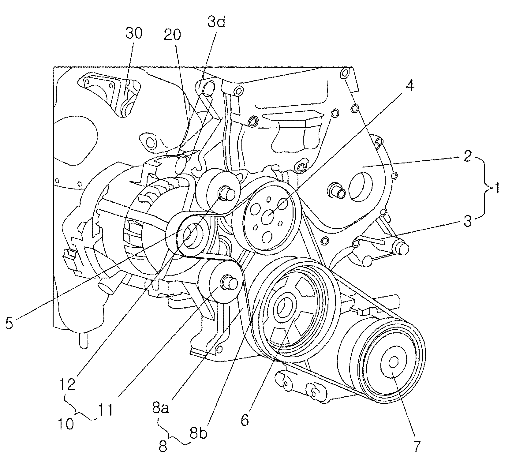
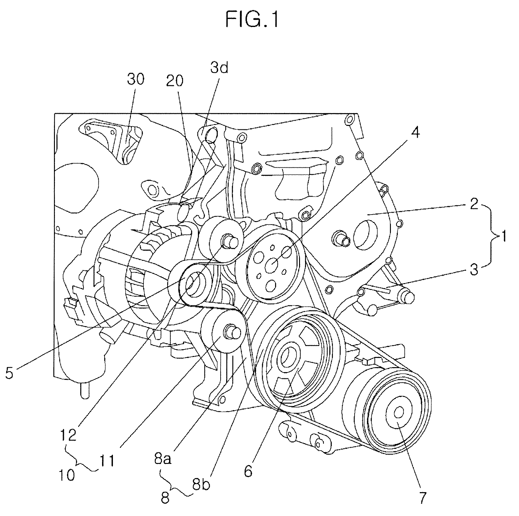
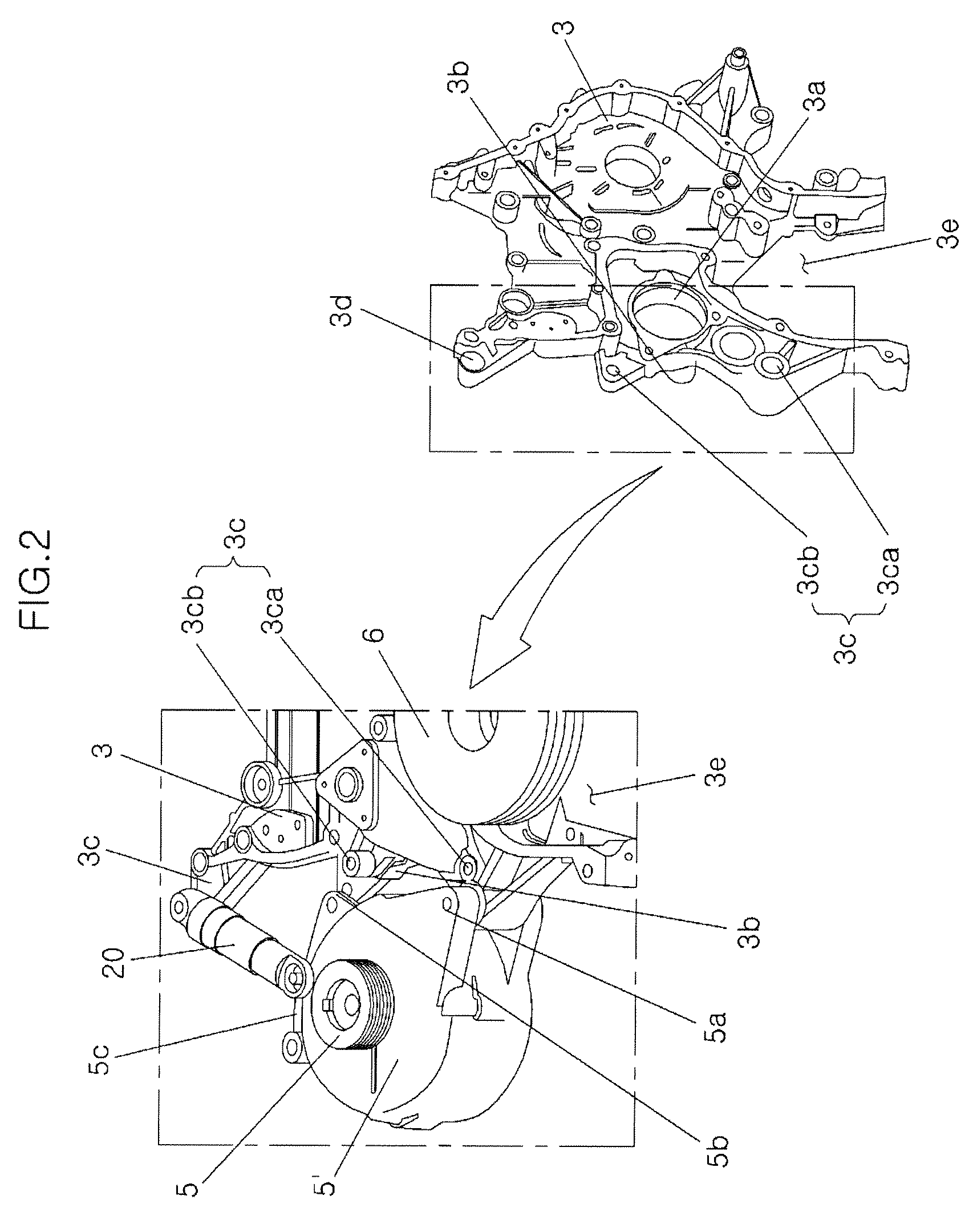
[0039]Referring to FIG. 1, an exemplary Belt Driven Electric Starter System (BES) includes an engine plate 1 that is attached to an engine 30, a pulley unit arranged with a predetermined layout at engine plate 1 with respect to a crank pulley 6 fitted on the crankshaft of the engine, a belt 8 transmitting power of crank pulley 6 to th...


PUM


Abstract

A Belt Driven Electric Starter System (BES) may have an idle pulley is composed of pivot point idle pulley forming pivot points at both sides of driving belt, which is wound on starter generator pulley and crank pulley, and driven idle pulley forming the fixing point, and a side of tension controller is fixed to engine and the opposite side is fixed to starter generator combined with starter generator pulley, such that it is possible to more effectively use the empty space without interference with the other portions in the entire layout of the BES. Further, excessive tension of driving belt due to starter generator when the engine is started can be attenuated by retraction of tension controller that moves with starter generator, while the excessive tension of driving belt due to crank pulley when electricity is generated can also be attenuated by extension of tension controller that moves with starter generator.

Description

CROSS-REFERENCE TO RELATED APPLICATIONS[0001]The present application claims priority of Korean Patent Application Number 10-2011-0065807 filed Jul. 4, 2011, the entire contents of which application is incorporated herein for all purposes by this reference.BACKGROUND OF INVENTION[0002]1. Field of Invention[0003]The present invention relates to a vehicle with an Idle Stop and Go (ISG) function, and more particularly, to a belt-driven electric starter system that can improve fuel efficiency by optimally adjusting a tension of a belt for engine's auxiliary components and improve durability with reduction of a noise.[0004]2. Description of Related Art[0005]In general, a belt-driven electric starter system for auxiliary components of an engine can contribute to improving fuel efficiency and NVH in accordance with the layout.[0006]In particular, the layout of Belt driven electric starter system (BES) is considered as a very important factor in improving fuel efficiency and Noise, Vibration...

Claims


Application Information

Patent Timeline
Patent Type & Authority Patents(United States)
IPC IPC(8): F16H7/14F02N11/00
CPCF02N11/0814F02N15/02F02N11/04F02N15/006F02N15/08F16H7/14F16H2007/0802F02B67/06F02D29/02F16H7/08F16H7/20
Inventor LEE, JONGWONKIM, HYOUNGHYOUN
Owner HYUNDAI MOTOR CO LTD
Learn More