LED bulb

a technology of led bulbs and bulb bodies, applied in the direction of semiconductor devices for light sources, lighting and heating apparatus, lighting support devices, etc., can solve the problems of b>12/b> not efficiently cooling down and becoming subject to ignition, so as to facilitate a convenient replacement and reduce the occurrence of ignition. , the effect of rapid dissipation

Inactive Publication Date: 2014-04-08
LEE CHUN HSIEN
View PDF3 Cites 1 Cited by
  • Summary
  • Abstract
  • Description
  • Claims
  • Application Information

AI Technical Summary

Benefits of technology

[0006]The object of the present invention is to provide an LED bulb that can facilitate a convenient replacement without changing the typical appearance, attain a swift dissipation, and decrease the occurrence of ignition as a result of the over-heated LED bulb.
[0007]The present invention essentially comprises a lamp housing, a lamp cap engaged with the lamp housing, a core tube disposed inside the lamp housing, LED plates mounted on the core tube, and a controller controlling an on-off operation of the LED plates; wherein, the controller is arranged in a room of the core tube, which facilitates a direct substitution and allows adapting to the bulb having a typical appearance, thereby increasing the convenience of using. In addition, the core tube has one end thereof connected to the lam cap, so that the thermal produced by the LED plates could be radiated and dissipated through the core tube, the lamp cap, and the lamp housing. In addition to the dissipation, the present invention substantially prevents the ignition of the LED bulb while being subjected to a high temperature.

Problems solved by technology

In this manner, the base 12 may not efficiently cool down if the LED bulb 1 still lasts the lighting and the production of thermal and may become subject to ignition when the circuit panel 17 and the LED plates 15 are over heated under the high temperature, thus still requiring improvements.

Method used


Image

  • LED bulb
  • LED bulb
  • LED bulb

Examples


Embodiment Construction

[0016]Before the present invention is described in greater detail, it should be noted that the like elements are denoted by the same reference numerals throughout the disclosure.

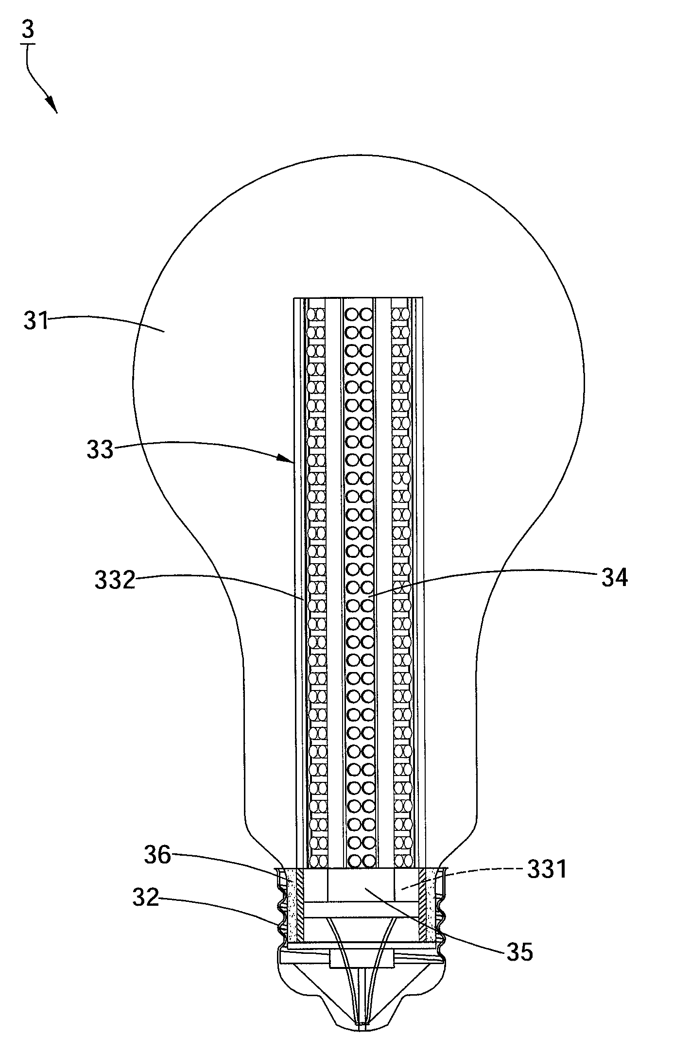
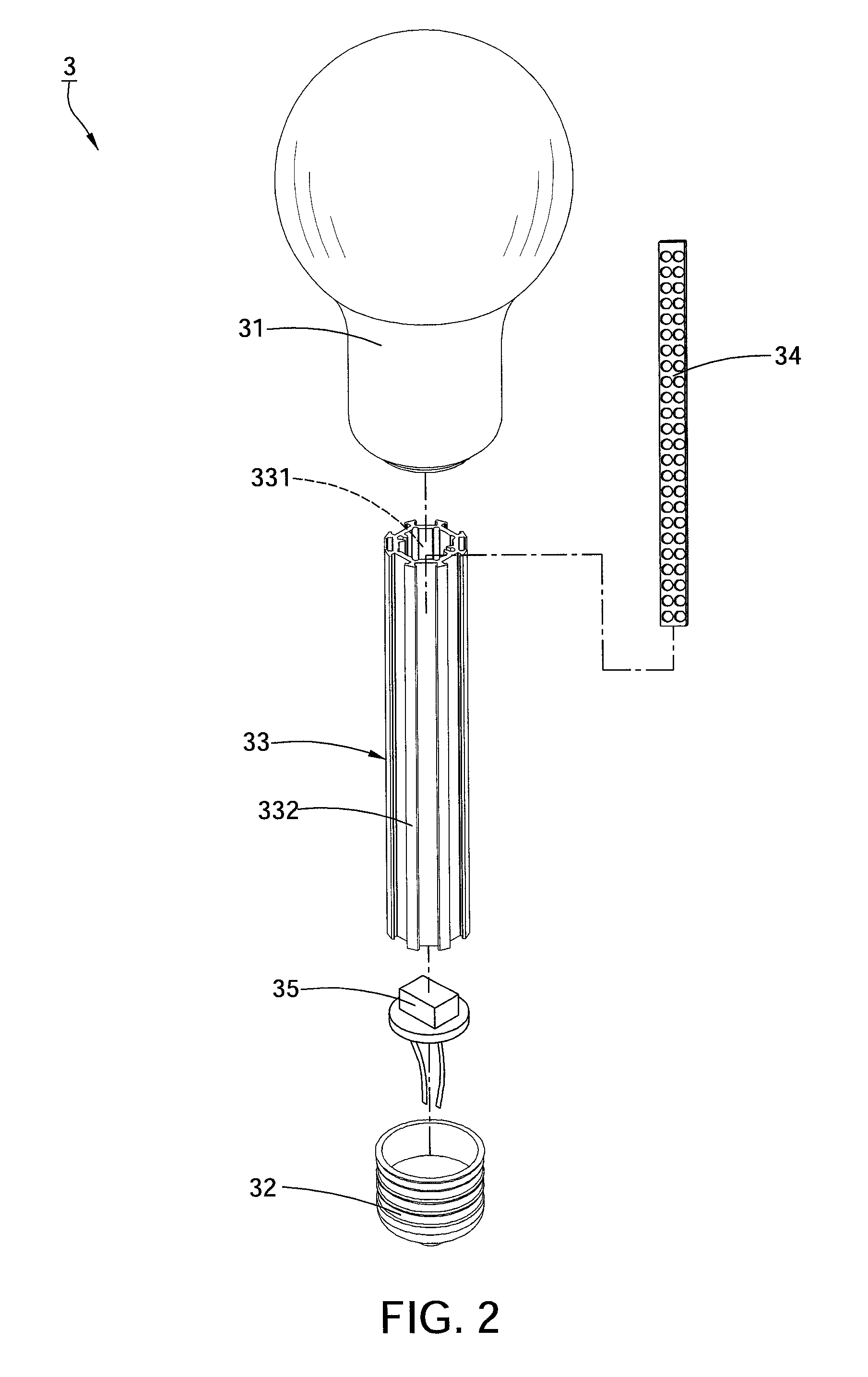
[0017]FIGS. 2 and 3 show a first preferred embodiment of the present invention. An LED bulb 3 in accordance with the present invention comprises a lamp housing 31, a lamp cap 32 engaged with the lamp housing 31, a core tube 33 disposed inside the lamp housing 31, a plurality of LED plates 34 mounted on the core tube 33, and a controller 35 controlling an on-off operation of the LED plates 34; wherein, the core tube 33 defines a room 331 at a central thereof for accommodating the controller 35. Herein, the core tube 33 can be formed by any feasible contours, for example, an octagonal core tube 33 is performed in the figures. Preferably, there are multiple ribs 332 defining on an outer periphery of the core tube 33 for engaging with and positioning the LED plates 34. Furthermore, the core tube 33 has one end t...


PUM


Abstract

An LED bulb comprises a lamp housing, a lamp cap, a core tube disposed inside the lamp housing, a plurality of LED plates mounted on the core tube, and a controller serving to manipulate an on-off operation of the LED plates. Wherein, the controller is substantially disposed inside a room of the core tube, and the core tube has one end thereof connected to the lamp cap, so as to facilitate a free substitution of the controller and promote the using convenience. The connection of the core tube and the lamp cap serves to radiate the thermal created by the LED plates from the core tube toward the lamp cap and the lamp housing for a speedy dissipation and preventing from burning the LED bulb under a high temperature.

Description

BACKGROUND OF THE INVENTION[0001]1. Field of the Invention[0002]The present invention relates to a bulb structure, particularly to an LED bulb with the preferable heat dissipation.[0003]2. Description of the Related Art[0004]FIG. 1 discloses a conventional LED bulb 1. The LED bulb 1 includes a head 11, a base 12 attached to the head 11, a shield 13 disposed above the base 12, a core tube 14 located inside the shield 13, multiple LED plates 15 disposed on the core tube 14, a core base 16 inside the base 12 connected to the core tube 14, and a circuit panel 17 electrically connected to the core base 16. Wherein, the core tube 14 is formed into a hollow configuration by centralizing with respect to an axis. On the core tube 14, a plurality of recesses 141 are defined for an embedment of the LED plates 15. The disposition of the core tube 14 is specialized in lighting; the hollow core tube 14 along with the core base 16 assists in radiating the ensued heat or thermal, therefore the conv...

Claims


Application Information

Patent Timeline
Patent Type & Authority Patents(United States)
IPC IPC(8): F21S4/00F21V21/00
CPCF21K9/135F21Y2101/02F21Y2111/005F21K9/232F21Y2115/10F21Y2107/30
Inventor LEE, CHUN-HSIEN
Owner LEE CHUN HSIEN
Why Eureka
Try Eureka