Photovoltaic roofing elements, photovoltaic roofing systems, methods and kits

a technology of photovoltaic roofing and photovoltaic roofing elements, applied in the direction of pv power plants, transportation and packaging, sustainable buildings, etc., can solve the problems of difficult integration with thin roofing products like asphalt or bituminous roofing shingles, bulky connectors with safety locks, and increased cost of fossil fuels. , to achieve the effect of improving the aesthetic look and reducing the stress/wear points of the roo

Active Publication Date: 2014-04-15
CERTAIN TEED LLC
View PDF38 Cites 32 Cited by
  • Summary
  • Abstract
  • Description
  • Claims
  • Application Information

AI Technical Summary

Benefits of technology

[0048]The photovoltaic roofing elements, systems and kits of the present invention can result in a number of advantages. The inventors have determined that even when the roofing substrate is relatively thin and flexible (e.g., an asphalt or bituminous roofing shingle), even a low profile or flatter style of connector can be thicker than the roofing substrate. In such cases, the connector can telegraph its structure to the top surface of the roofing substrate, resulting in an undesirably wavy or distorted appearance. Local telegraphing of bumps over these electrical connectors can also lead to stress points and wear points on or in the roofing substrate, causing a deleterious effect on product performance. In some aspects, this invention solves the problem of electrical connectors telegraphing shapes through to the top surface of thin flexible roofing products equipped with photovoltaic media. This can help improve the aesthetic look and reduce stress / wear points of a roof equipped with the photovoltaic roofing elements and photovoltaic roofing systems of the present invention. Other advantages will be apparent to the person of skill in the art.

Problems solved by technology

First, fossil fuels have become increasingly expensive due to increasing scarcity and unrest in areas rich in petroleum deposits.
Second, there exists overwhelming concern about the effects of the combustion of fossil fuels on the environment due to factors such as air pollution (from NOx, hydrocarbons and ozone) and global warming (from CO2).
In some cases, bulky connectors with safety locks may be required depending on the accessibility of the electrical connection.
There exist low-profile connectors, but even these can be difficult to integrate with thin roofing products like asphalt or bituminous roofing shingles.

Method used


Image

  • Photovoltaic roofing elements, photovoltaic roofing systems, methods and kits
  • Photovoltaic roofing elements, photovoltaic roofing systems, methods and kits
  • Photovoltaic roofing elements, photovoltaic roofing systems, methods and kits

Examples


Embodiment Construction

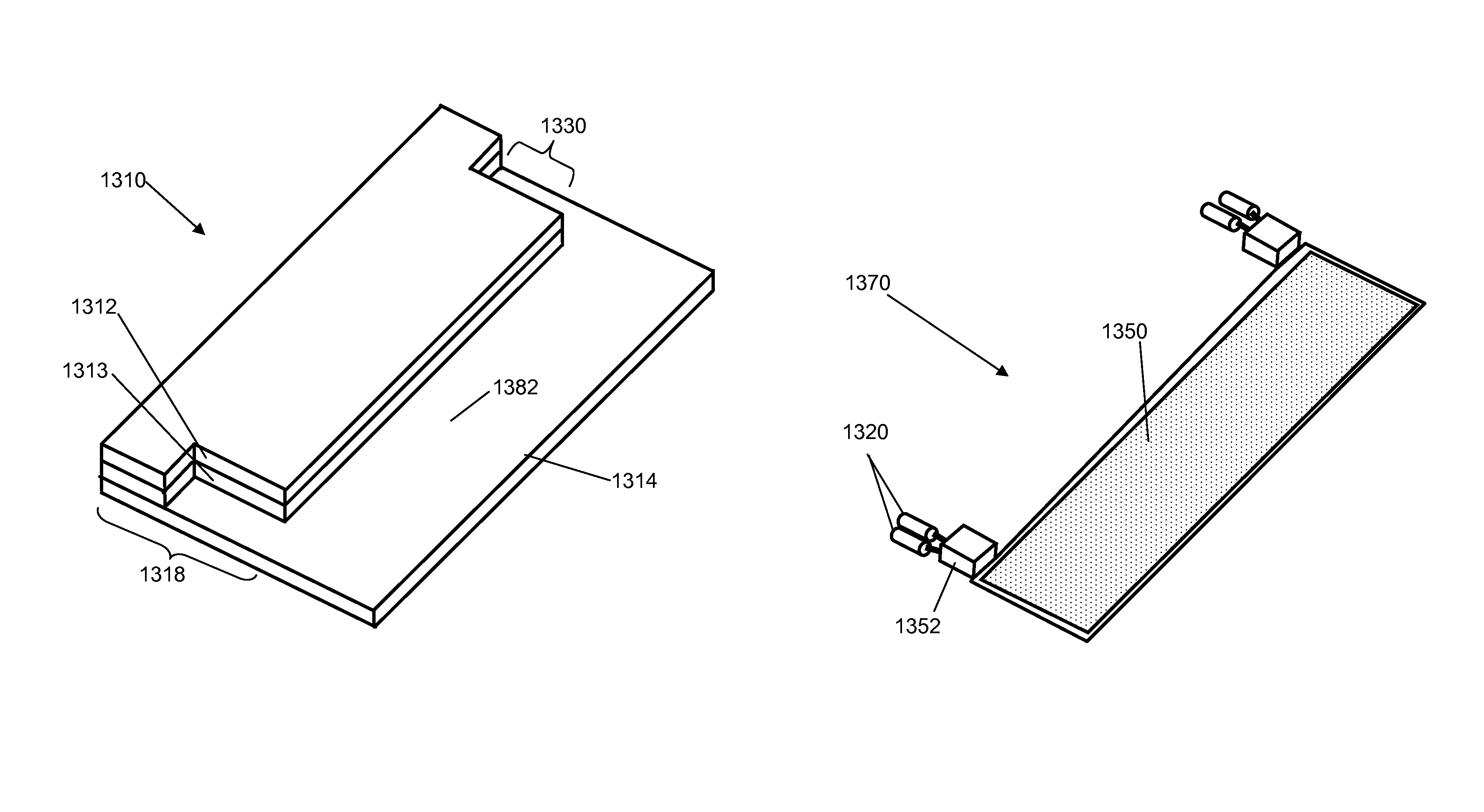
[0075]One aspect of the invention is a photovoltaic roofing element comprising a flexible roofing substrate; a photovoltaic element disposed on the flexible roofing substrate; and an electrical connector operatively coupled to the photovoltaic element, wherein the roofing substrate has formed therein a recess shaped to at least partially receive the electrical connector. The recess can be formed, for example, in a top or a bottom surface of the photovoltaic roofing element, or along a side of the photovoltaic roofing element (e.g., as a “notch” or a “cutout”).

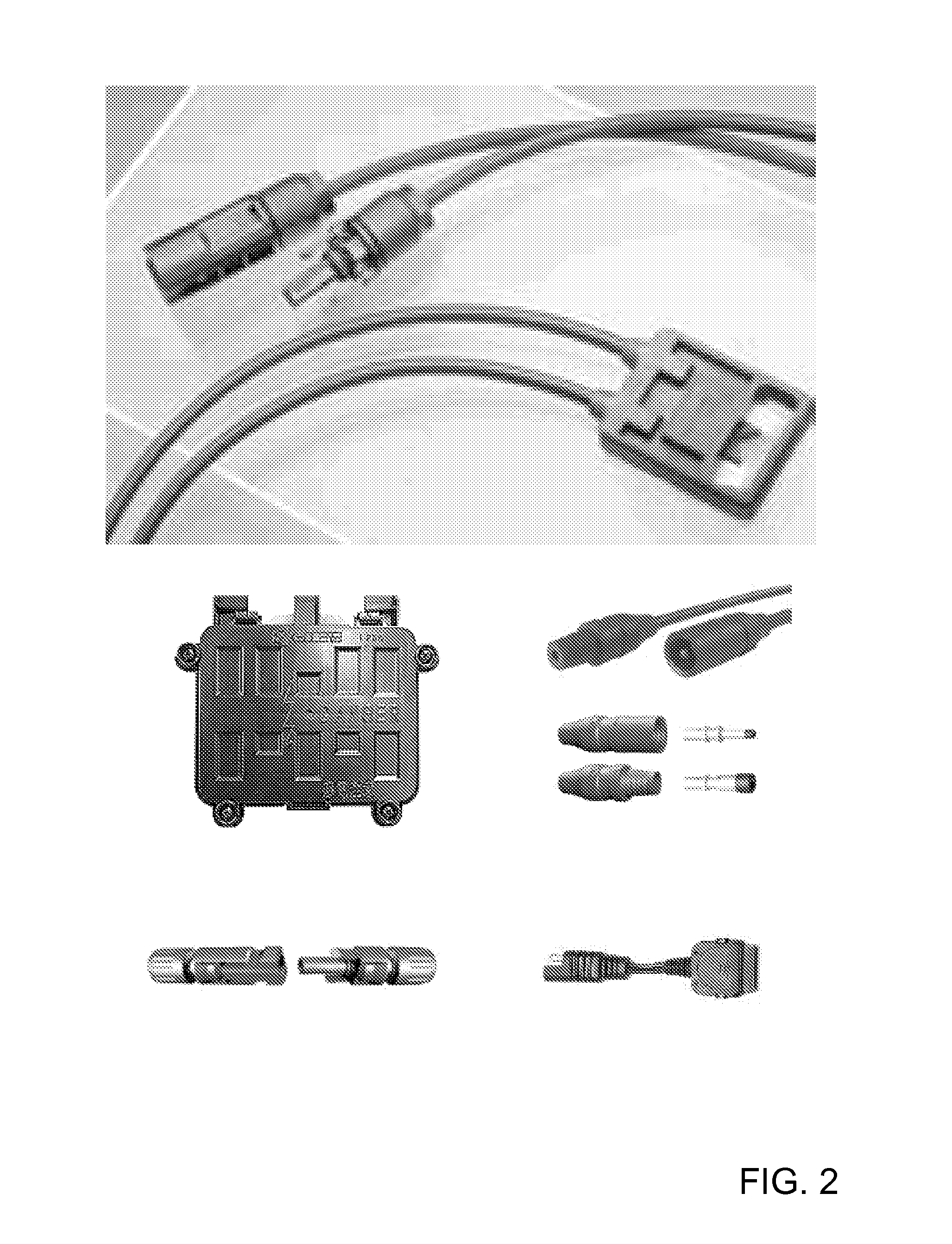
[0076]The electrical connector can be disposed in the recess. For example, the electrical connector can in certain embodiments be affixedly disposed in the recess. For example, the electrical connector can be a junction box affixedly disposed in the recess. In other embodiments, the electrical connector can be generally movable with respect to the recess, and disposed in the recess when the photovoltaic roofing element is insta...


PUM


Abstract

The present invention relates generally to the photovoltaic generation of electrical energy. The present invention relates more particularly to photovoltaic roofing products for use in photovoltaically generating electrical energy. One aspect of the invention is a photovoltaic roofing element comprising: a flexible roofing substrate; a photovoltaic element disposed on the flexible roofing substrate; and an electrical connector operatively coupled to the photovoltaic element, wherein the flexible roofing substrate has formed therein a recess shaped to at least partially receive the electrical connector.

Description

CROSS-REFERENCE TO RELATED APPLICATIONS[0001]This application claims priority under 35 U.S.C. §119(e) to U.S. Provisional Patent Application Ser. No. 61 / 121,130, filed Dec. 9, 2008, and U.S. Provisional Patent Application Ser. No. 61 / 238,566, filed Aug. 31, 2009, each of which is hereby incorporated herein by reference in its entirety.BACKGROUND OF THE INVENTION[0002]1. Field of the Invention[0003]The present invention relates generally to the photovoltaic generation of electrical energy. The present invention relates more particularly to photovoltaic roofing products for use in photovoltaically generating electrical energy.[0004]2. Technical Background[0005]The search for alternative sources of energy has been motivated by at least two factors. First, fossil fuels have become increasingly expensive due to increasing scarcity and unrest in areas rich in petroleum deposits. Second, there exists overwhelming concern about the effects of the combustion of fossil fuels on the environmen...

Claims


Application Information

Patent Timeline
Patent Type & Authority Patents(United States)
IPC IPC(8): E04D13/18
CPCH01L31/05Y02E10/50Y02B10/12H01L31/0483H02S40/36H02S20/25H01L31/044Y10T428/24752E04D1/26Y02B10/10Y02B10/20H01L31/048
Inventor KOCH, STEVEN A.KALKANOGLU, HUSNU M.JACOBS, GREGORY F.SHAW, WAYNE E.JENKINS, ROBERT L.LIVSEY, ROBERT D.
Owner CERTAIN TEED LLC
Why Eureka
Try Eureka