Systems and methods for splicing solar panel racks

a solar panel and rack technology, applied in the field of systems and methods for splicing solar panel racks, can solve problems such as not being as strong as the rails themselves

Active Publication Date: 2014-04-15
IRONRIDGE
View PDF52 Cites 81 Cited by
  • Summary
  • Abstract
  • Description
  • Claims
  • Application Information

AI Technical Summary

Benefits of technology

[0015]4. More pleasing aesthetics. Utilizing an internal splice provides a more pleasing vi

Problems solved by technology

Although the external splice provides some structural s

Method used


Image

  • Systems and methods for splicing solar panel racks
  • Systems and methods for splicing solar panel racks
  • Systems and methods for splicing solar panel racks

Examples


Embodiment Construction

[0040]While preferred embodiments of the invention have been shown and described herein, it will be obvious to those skilled in the art that such embodiments are provided by way of example only. Numerous variations, changes, and substitutions will now occur to those skilled in the art without departing from the invention. It should be understood that various alternatives to the embodiments of the invention described herein may be employed in practicing the invention.

I. Solar Rack Assembly

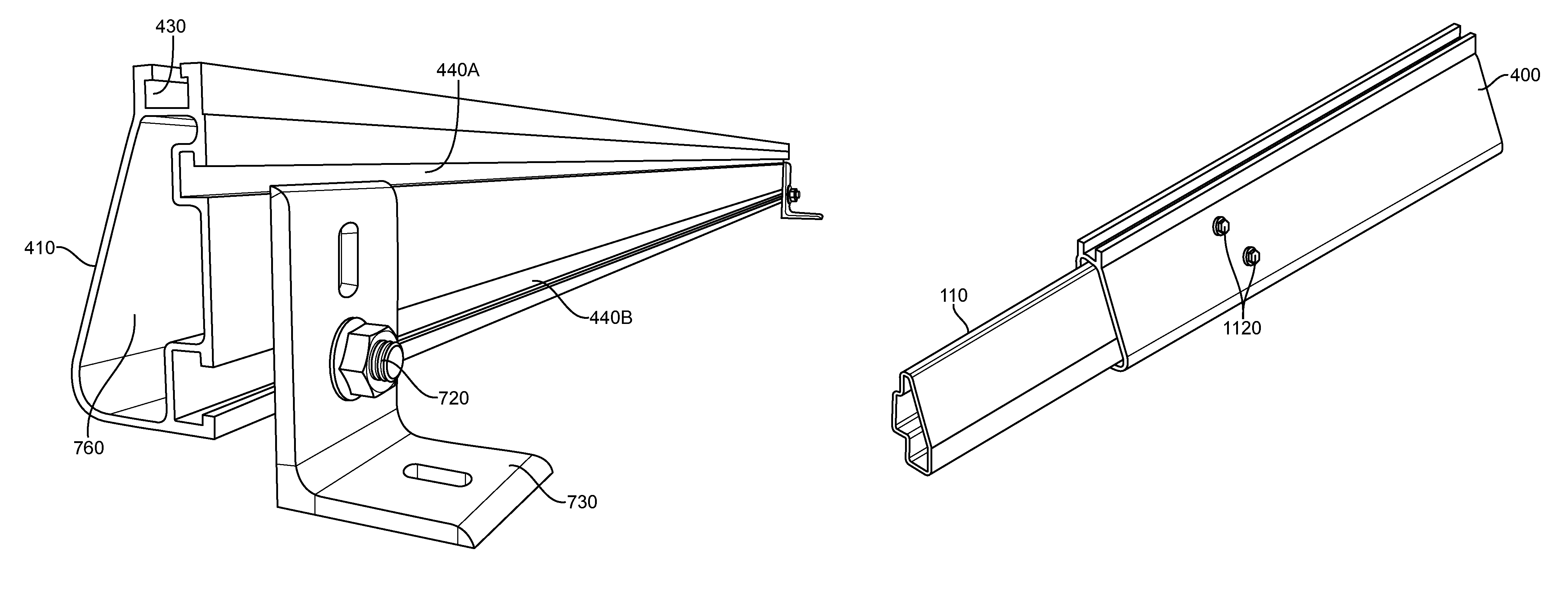
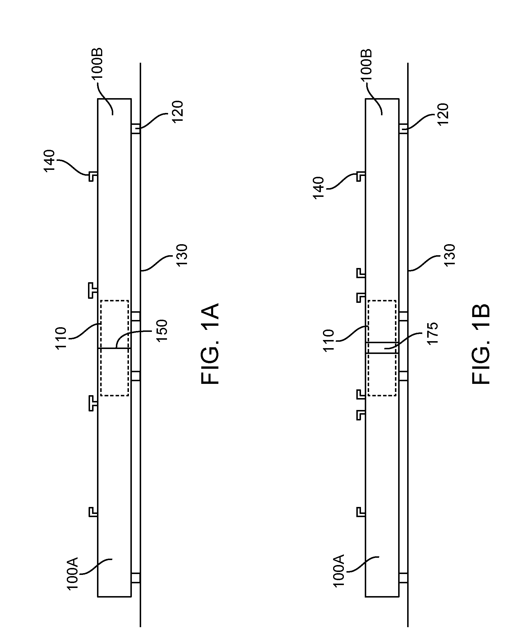
[0041]FIG. 1A shows a side view of a solar rack in accordance with an embodiment of the invention. A solar rack may include a first solar rack section 100A and a second solar rack section 100B. The solar rack sections may be connected by an internal rack splice 110. The solar rack may be provided on a support surface 130 and may optionally be connected to the support surface via one or more rack anchor 120. One or more solar module securing component 140 may be provided on the solar rack. A solar mo...


PUM

PropertyMeasurementUnit
Weightaaaaaaaaaa

Abstract

The invention provides systems and methods for splicing solar panel racks. Solar panel racks may include one, two, or more solar rack sections that may be connected to one another with an internal splice. The internal splice may internally support the adjoining solar racks. The solar rack may be secured to a support surface using one or more feet. The solar panel racks may be configured to support the weight of one or more solar modules. One or more solar module securing component may be used to secure the solar modules to a solar rack surface.

Description

CROSS-REFERENCE[0001]This application claims the benefit of U.S. Provisional Application No. 61 / 267,409, filed Dec. 7, 2009, which application is incorporated herein by reference in its entirety.BACKGROUND OF THE INVENTION[0002]Solar electric systems are an environmentally friendly way of generating electricity. Such solar electric systems typically include a solar module having a photovoltaic panel and a solar module frame. The solar modules may be assembled and / or installed on a surface, such as the roof of a building, the ground, or other support structure, such as a pole or pole mounted frame.[0003]A solar module mounting system may include one or more components that may be desired at long dimensions. Components with long dimensions may be cumbersome to transport and / or install. Some previous systems have attempted to simplify installation by providing solar module frames that can be assembled from multiple components or solar modules whose frames may connect directly to one an...

Claims


Application Information

Patent Timeline
IPC IPC(8): E04D13/18
CPCH01L31/0482F24J2/52F24J2/5252Y02B10/12F24J2/5262Y02B10/20Y02E10/47Y02E10/50Y10T29/49616Y10T403/55F24S25/63F24S25/67Y02B10/10
Inventor KIM, WILLIAMCARNI, CRAIGZUIDEMA, VICTOR
Owner IRONRIDGE
Why Eureka
Try Eureka