Automatic displacer clearance adjustment

a technology of displacer and adjustment device, which is applied in the direction of sausage casing, sausage casing shirring, butchering, etc., can solve the problems of sensitive casing material or “normal” casing material which is filled with sausage meat at high pressure and may be damaged during the constricting process, and achieve the effect of raising the production efficiency of sausage like products

Active Publication Date: 2014-04-15
POLY CLIP SYST
View PDF10 Cites 2 Cited by
  • Summary
  • Abstract
  • Description
  • Claims
  • Application Information

AI Technical Summary

Benefits of technology

[0008]The object of the present invention is to solve the above described problem. In particular, it is the object of the present invention to provide an apparatus according to independent claim 1 and a method according to independent claim 10 for producing a plait-like portion on a tubular packaging casing, with which the risk of damaging the casing material while constricting said material and forming a plait-like portion will be reduced and the productivity in the production of sausage like products is raised.
[0011]Also, adapting the size of the displacer clearance depending on e.g. the sensitivity of casing material or the caliber of the sausage product to be produced, reduces the risk of damaging while gathering the casing material and forming the plait-like portion.
[0012]It is advantageous that the adjustment device comprises a drive element and a two-armed lever which are coupled to each other by a torque transmission element in order to transmit the motion of the drive mechanism via a drive arm to the displacer units. The transmission of the motion from a drive mechanism to the displacer units can alternatively be done by a chain-drive, gear-drive, belt-drive or any other possible means of transmission. The torque transmission element can be in form of a sliding block or likewise, to permit the drive element and the two-armed lever to be shifted relative to each other while allowing a continuously transmission of torque. In order to support this, it is also favorably that the torque transmission element is attached to the two-armed lever and is extending into a radial aligned guide being part of the drive element, to allow the torque transmission element to continuously transmit torque from the drive element to the two-armed lever, even if the two-armed lever varies its position relative to the drive element.
[0019]In accordance with the present invention, the method further comprises the step of changing the size of the displacer clearance created by the first and second pair of displacer elements by adjusting a pivot axis of an adjustment device. By changing the size of the displacer clearance, the risk of damaging in particular sensitive casing material may be reduced. Moreover, an adaption may be made to the caliber of the sausage-like product to be produced e.g., in case of a larger caliber of the sausage product, to the additional casing material forming a plait-like portion of a respectively larger diameter.
[0021]The above mentioned features of the inventive method allow an automatically adjustment of the adjustment device on the basis of data regarding pre-selected products. The adjustment of the size of the displacer clearance by means of the adjustment device may even be done during on-going production without having to stop the sausage-product manufacturing process. Thereby, the sausage production may be improved and increased. In particular, the voiding of the filling material from the plait-like portion will be optimized. Moreover, the risk of damaging the casing material will be minimized while maintaining a constant or higher production rate.

Problems solved by technology

However, in case of a tightly filled sausage product, these sausage products are rather prone to damages on the casing, due to the high pressure inside the sausage product and the often thin and sensitive casing material.
Impacts, falls and other kinds of careless handling can result inevitable in notable damages to the sausage products, which lead to outcast and unnecessary costs.
A particular problem in this context constitutes within the actual procedure of constricting the casing by means of the two displacer units and forming the plait-like portion out of the tubular packaging casing.
Depending on the above mentioned parameters, in particular, sensitive casing material or “normal” casing material which is filled with sausage meat at high pressure may be damaged during the constricting process when executed at a “normal” speed.
Moreover, the casing material may be also damaged during forming the plait-like portion.

Method used


Image

  • Automatic displacer clearance adjustment
  • Automatic displacer clearance adjustment
  • Automatic displacer clearance adjustment

Examples


Embodiment Construction

[0029]The embodiment of the inventive apparatus described in the following is used within clipping machines for the production of sausage products. The inventive apparatus may also be used, of course, in production of sausage-shaped products that are not foodstuffs, but for example, sealing compounds or adhesives.

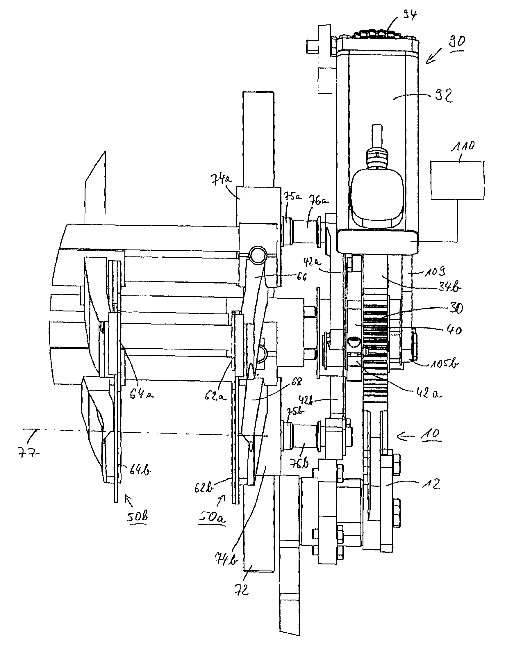
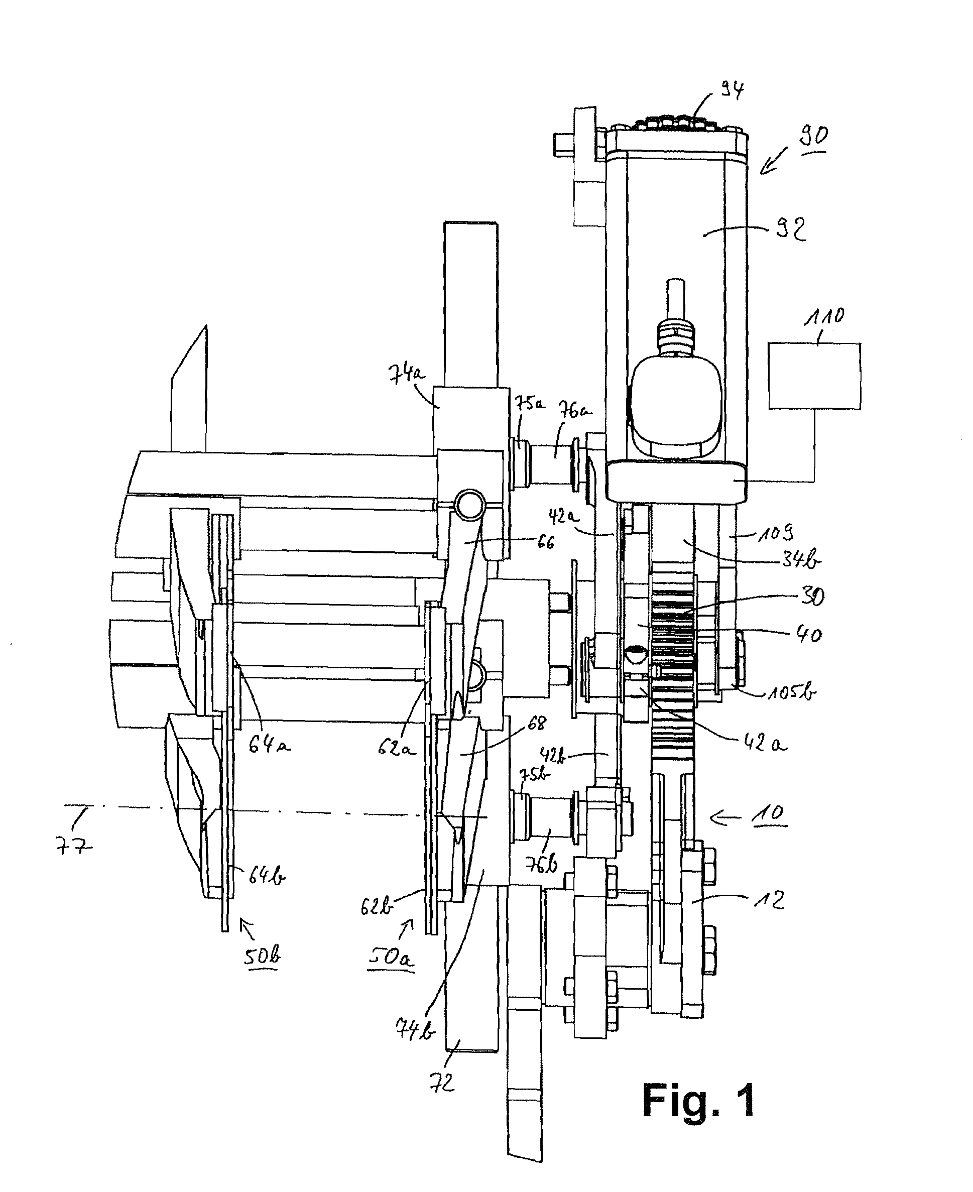
[0030]FIG. 1 shows a schematic front view of the inventive apparatus according to a preferred embodiment in perspective direction perpendicular to a longitudinal plait-axis 77, together with first and second drive units 10, 90, a first displacer unit 50a having a first pair of displacer elements 60a and a second displacer unit 50b having a second pair of displacer elements 60b. The first and second displacer units 50a, 50b are actuated by the first drive unit 10 for a reversible movement perpendicular to the plait-axis 77 along vertical displacer guide rods. FIG. 1 shows only the first displacer guide rod 72 along which the first pair of displacer elements 60a is vertically...


PUM


Abstract

An apparatus and method producing a plait-like portion on a tubular packaging casing, which accommodates a filling material includes a plait-like portion at least approximately free of filling material, extending along a longitudinal plait-axis. The apparatus comprises a first displacer unit with a first pair of displacer elements reversibly movable between an opened and a closed position perpendicular to the longitudinal plait-axis. A displacer clearance is created between the first pair of displacer elements, which surrounds the longitudinal plait-axis, in which the tubular packaging casing is being gathered, when the first pair of displacer elements is in the closed position. The apparatus comprises a second displacer unit with a second pair of displacer elements also being reversibly movable between an opened and a closed position perpendicular to the longitudinal plait-axis. A displacer clearance is created between the second pair of displacer elements, similar to first pair of displacer elements.

Description

CROSS REFERENCE TO RELATED APPLICATIONS[0001]This patent application claims priority to and the benefit of European patent application EP 09 015 524.3-1260, filed Dec. 15, 2009, which is hereby incorporated herein by reference.BACKGROUND OF THE INVENTION[0002]The present invention relates to an apparatus and a method for producing a plait-like portion on a tubular packaging casing according to the preamble of independent claims 1 and 10.[0003]In particular, the invention concerns an apparatus for producing a plait-like portion on a tubular packaging casing which accommodates a filling material in particular sausage meat, wherein the plait-like portion is at least approximately free of filling material and comprises along a longitudinal plait-axis. The apparatus comprises a first displacer unit with a first pair of displacer elements being reversibly movable perpendicular to the longitudinal plait-axis between an opened and a closed position. A displacer clearance is being created be...

Claims


Application Information

Patent Timeline
Patent Type & Authority Patents(United States)
IPC IPC(8): A22C13/02A22C11/00
CPCA22C11/10A22C11/105A22C11/104A22C11/108
Inventor EBERT, DETLEFHUMMEL, MICHAEL
Owner POLY CLIP SYST
Why Eureka
Try Eureka