High-speed automatic dispensing device with replaceable dispensing head and dispensing station

a technology of automatic dispensing and dispensing equipment, which is applied in the direction of analytical instruments, laboratory glassware, instruments, etc., can solve the problems of unadaptable pipette and the number of prepared samples, and achieve the effect of minimizing the amount of waste of liquid materials

Active Publication Date: 2014-04-15
MUSASHI ENG INC
View PDF16 Cites 8 Cited by
  • Summary
  • Abstract
  • Description
  • Claims
  • Application Information

AI Technical Summary

Benefits of technology

[0014]According to the present invention, by replacing the dispensing head, samples under different conditions can be prepared on one dispense plate by using one dispensing apparatus. Also, waste liquid materials can be minimized. On that occasion, by changing the amount of the liquid material discharged from the dispenser, samples can be prepared at composition ratios varying over various levels.
[0015]Further, by preparing a plurality of dispensing heads including the pipettes arranged thereon in the same number, even when the pipette head requires maintenance, the dispensing apparatus can be continuously operated with replacement of the dispensing head without interrupting the dispending operation for a long time.

Problems solved by technology

With the progress of medicines and biotechnology, the number of prepared samples is drastically increased to such an extent that one pipette is not adaptable for preparing so many samples.

Method used


Image

  • High-speed automatic dispensing device with replaceable dispensing head and dispensing station
  • High-speed automatic dispensing device with replaceable dispensing head and dispensing station
  • High-speed automatic dispensing device with replaceable dispensing head and dispensing station

Examples


embodiment 1

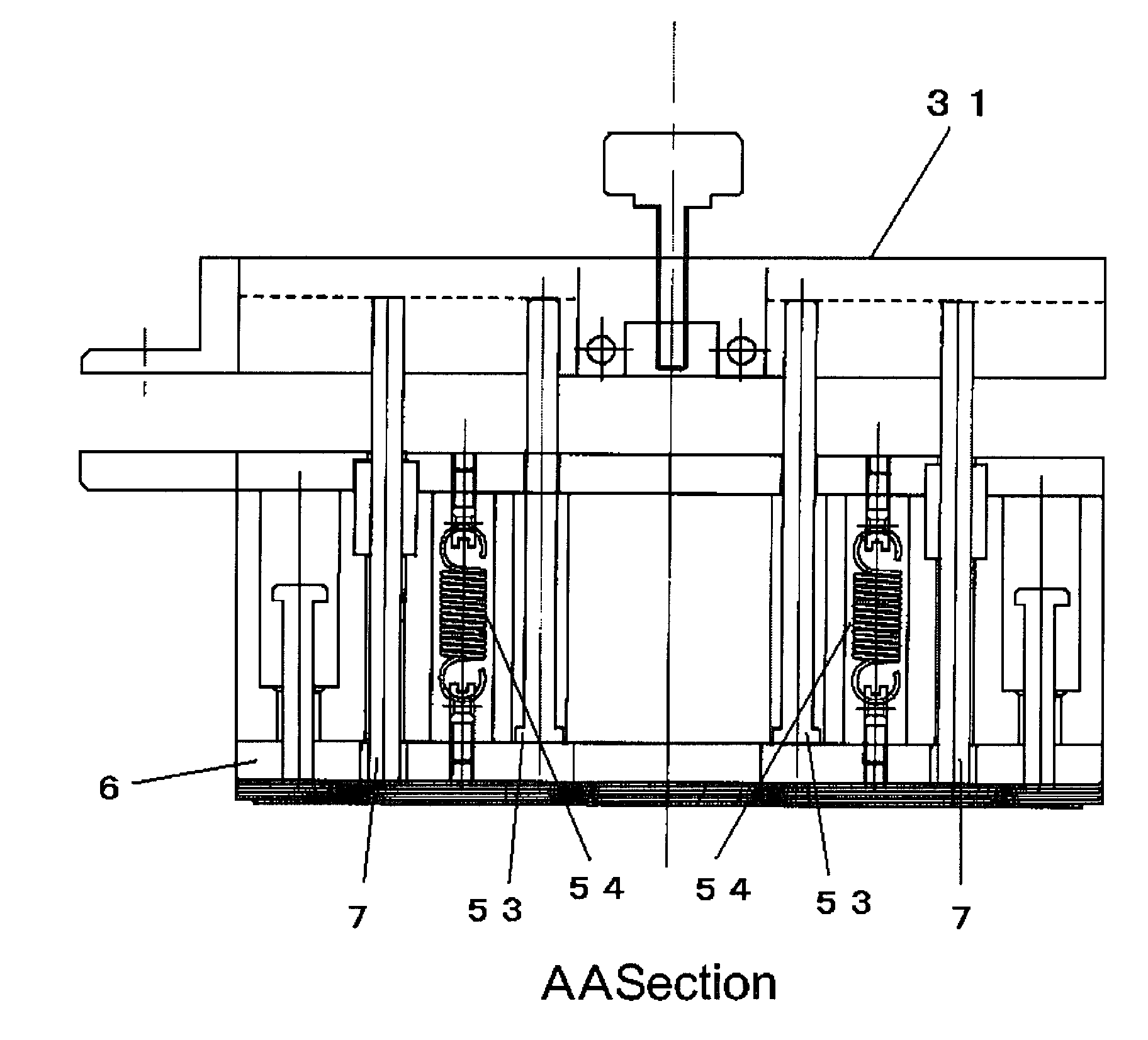
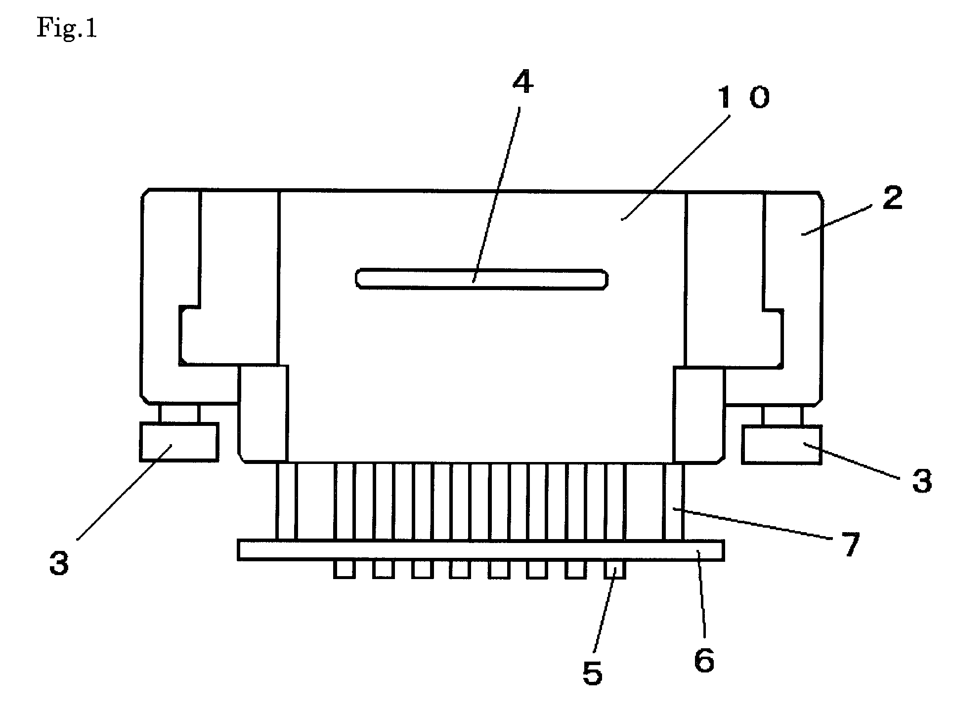
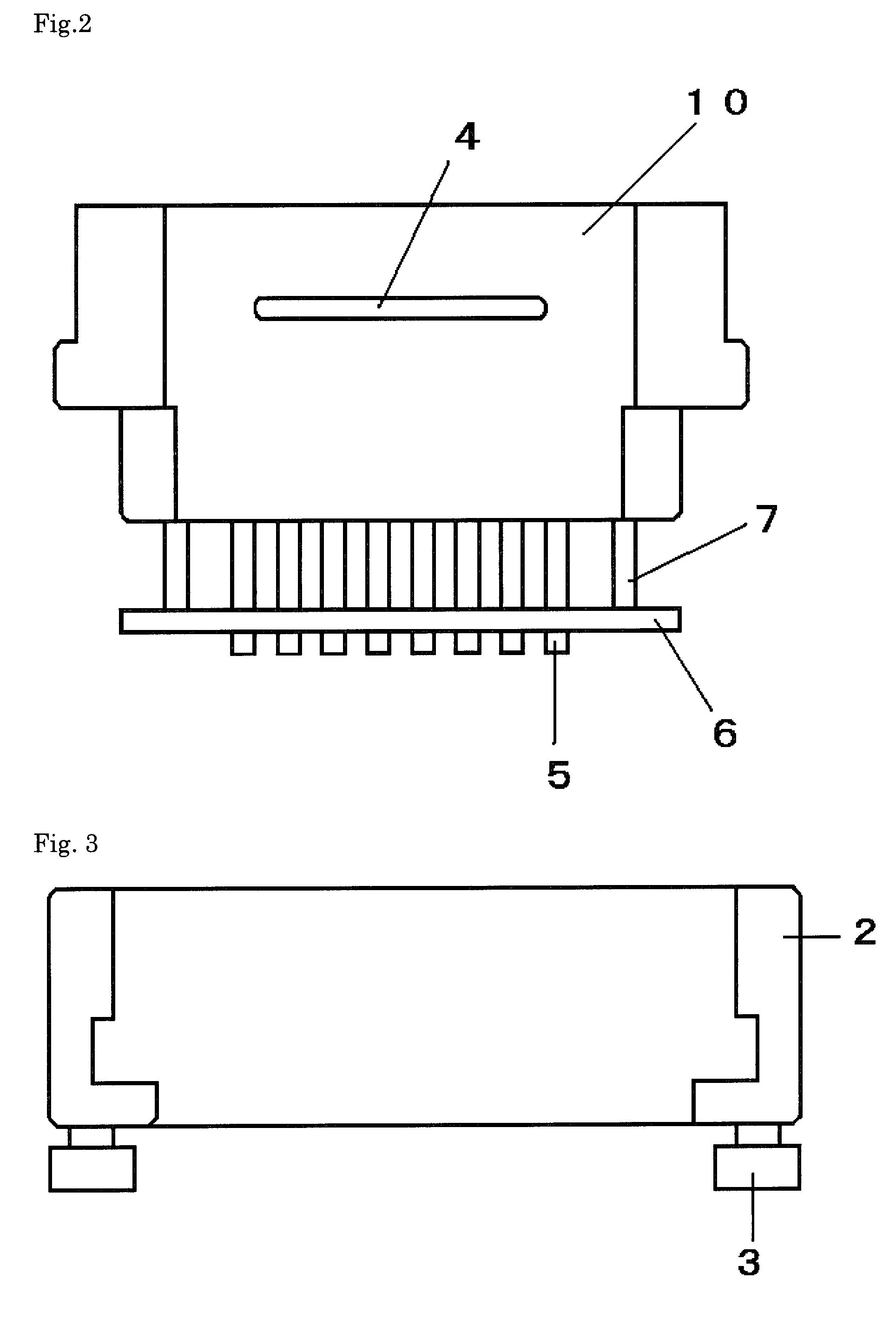
[0087]As shown in FIG. 1, the dispensing head 1 used in the dispensing apparatus of this embodiment comprises the body holder 2, the body connectors 3, the body grip 4, the pipettes 5 to which the tips are attached, the tip release plate 6 for releasing (detaching) the tips from the pipettes, and posts 7. The dispensing head has 96 pipettes (8 columns×12 rows) and is mounted to the body holder 2. FIG. 2 shows a state where the dispensing head 1 is removed from the body holder 2 by loosening the body connectors 3, and FIG. 3 shows the body holder 2 from which the dispensing head 1 is removed. FIG. 4 is a front view of a dispensing head having 12 pipettes (1 column×12 rows), which is also mounted to the body holder 2. It is to be noted that the pipette head 31 is omitted in FIGS. 1-4.

[0088]FIG. 11 shows a state where the dispensing head 1 is mounted to the head holder 44. The head holder 44 is coupled to a drive mechanism 15 for moving the head holder 44 in the vertical direction (i.e...

embodiment 2

[0097]Because the distal ends of the tips 8 are just required in Embodiment 1 to enter respective test tubes 20 on the dispense plate 11, the interval between the test tubes 20 can be further reduced. In this Embodiment 2, the test tubes 20 are arrayed at the interval that is a half the interval between the tips 8, to thereby increase the number of test tubes arrayed on the dispense plate. In other words, 384 test tubes (96×4; 16 columns×24 rows) are arrayed on one dispense plate having the same area as in Embodiment 1. Such an arrangement is effective in avoiding the disadvantages of excessively increasing the number of pipettes in match with the interval between the test tubes, reducing the dispensing accuracy with the use of smaller pipettes and tips, and causing a difficulty in alignment of the tips. To be adapted for the reduction of the interval between the test tubes to ½, the accuracy in alignment of the tips 8 has to be improved. Such a problem can be overcome by providing ...


PUM

PropertyMeasurementUnit
speedaaaaaaaaaa
lengthaaaaaaaaaa
thicknessaaaaaaaaaa

Abstract

A high-speed automatic dispensing apparatus capable of preparing samples under different conditions, minimizing waste liquid materials, and realizing high productivity. A dispensing station is also provided. The high-speed automatic dispensing apparatus with a replaceable dispensing head comprises a dispensing head including a plurality of pipettes, a pipette head to which one end of a plunger extending to pass through each pipette is fixed, and a head body part abutting against the pipette head and allowing the pipettes to pass therethrough, a pipette head moving mechanism vertically moving the pipette head, and a drive mechanism horizontally and vertically moving the dispensing head. The dispensing station includes the high-speed automatic dispensing apparatus.

Description

TECHNICAL FIELD[0001]The present invention relates to a high-speed automatic dispensing apparatus with a replaceable dispensing head, which can prepare samples under different conditions and minimize waste liquid materials. The present invention also relates to a dispensing station.BACKGROUND ART[0002]Hitherto, in experiments of, for example, mixing chemical materials including medicines or mixing organisms and chemical materials in the field of biotechnology, samples have been prepared by sucking a target liquid material with a pipette and pouring the sucked liquid material into a test tube or a reagent bottle. With the progress of medicines and biotechnology, the number of prepared samples is drastically increased to such an extent that one pipette is not adaptable for preparing so many samples. For the purpose of increasing productivity, the number of holes formed in a dispense plate (microplate) to receive the dispensed liquid material is also increased from 96 per plate to four...

Claims


Application Information

Patent Timeline
Patent Type & Authority Patents(United States)
IPC IPC(8): B01L3/02G01N1/14
CPCG01N35/1074G01N35/10G01N35/00
Inventor IKUSHIMA, KAZUMASA
Owner MUSASHI ENG INC
Why Eureka
Try Eureka