Battery module

a battery module and battery technology, applied in the field of batteries, can solve the problems of increasing the number of parts and increasing the cos

Active Publication Date: 2014-04-22
ENVISION AESC JAPAN LTD
View PDF18 Cites 7 Cited by
  • Summary
  • Abstract
  • Description
  • Claims
  • Application Information

AI Technical Summary

Benefits of technology

[0007]In view of the state of the known technology, one aspect of the present disclosure is to provide a battery module in which a uniform surface pressure can be applied without increasing the number of parts.

Problems solved by technology

Consequently, there is a concern that the number of parts and the cost will increase.

Method used


Image

  • Battery module
  • Battery module
  • Battery module

Examples


first embodiment

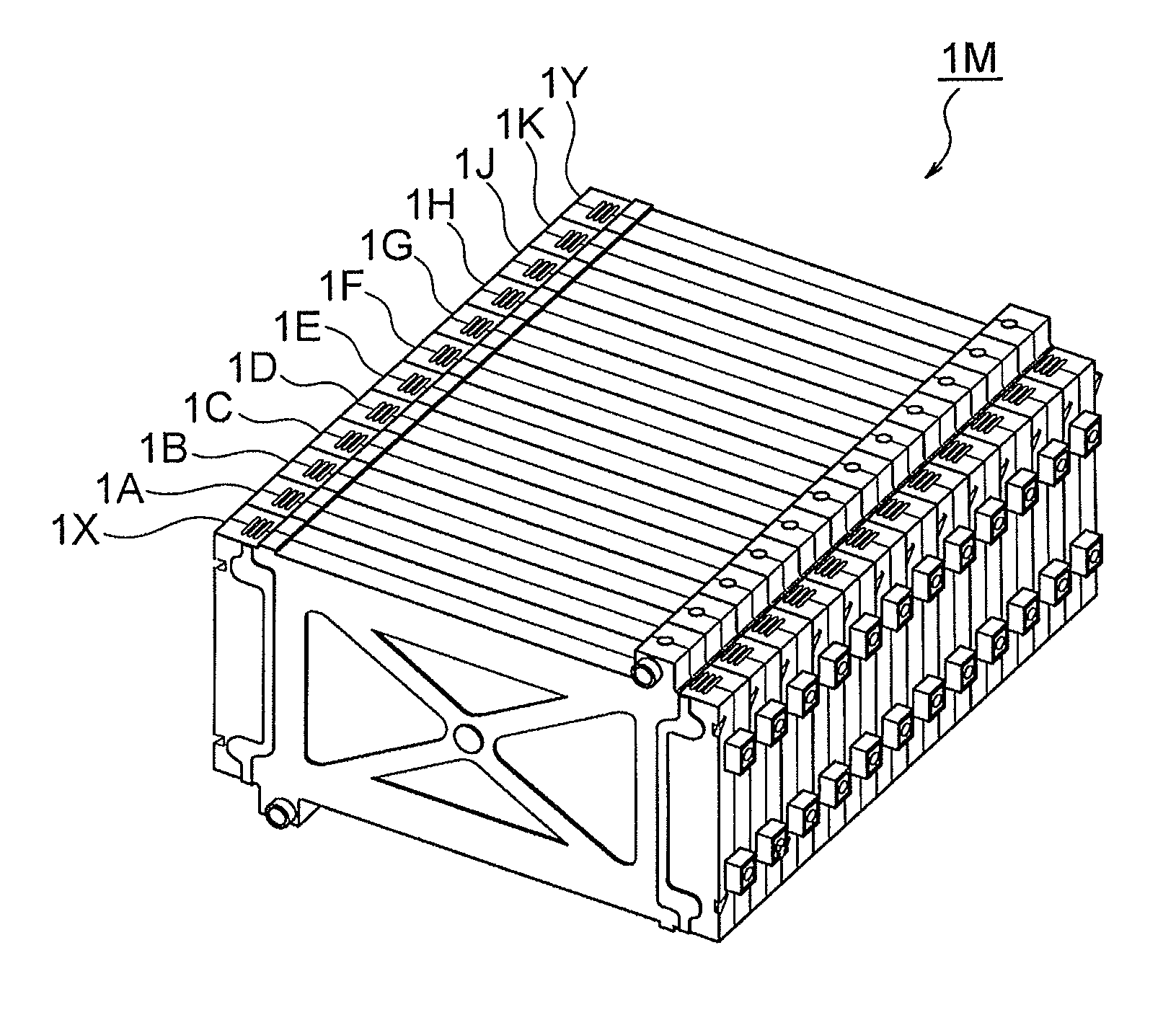
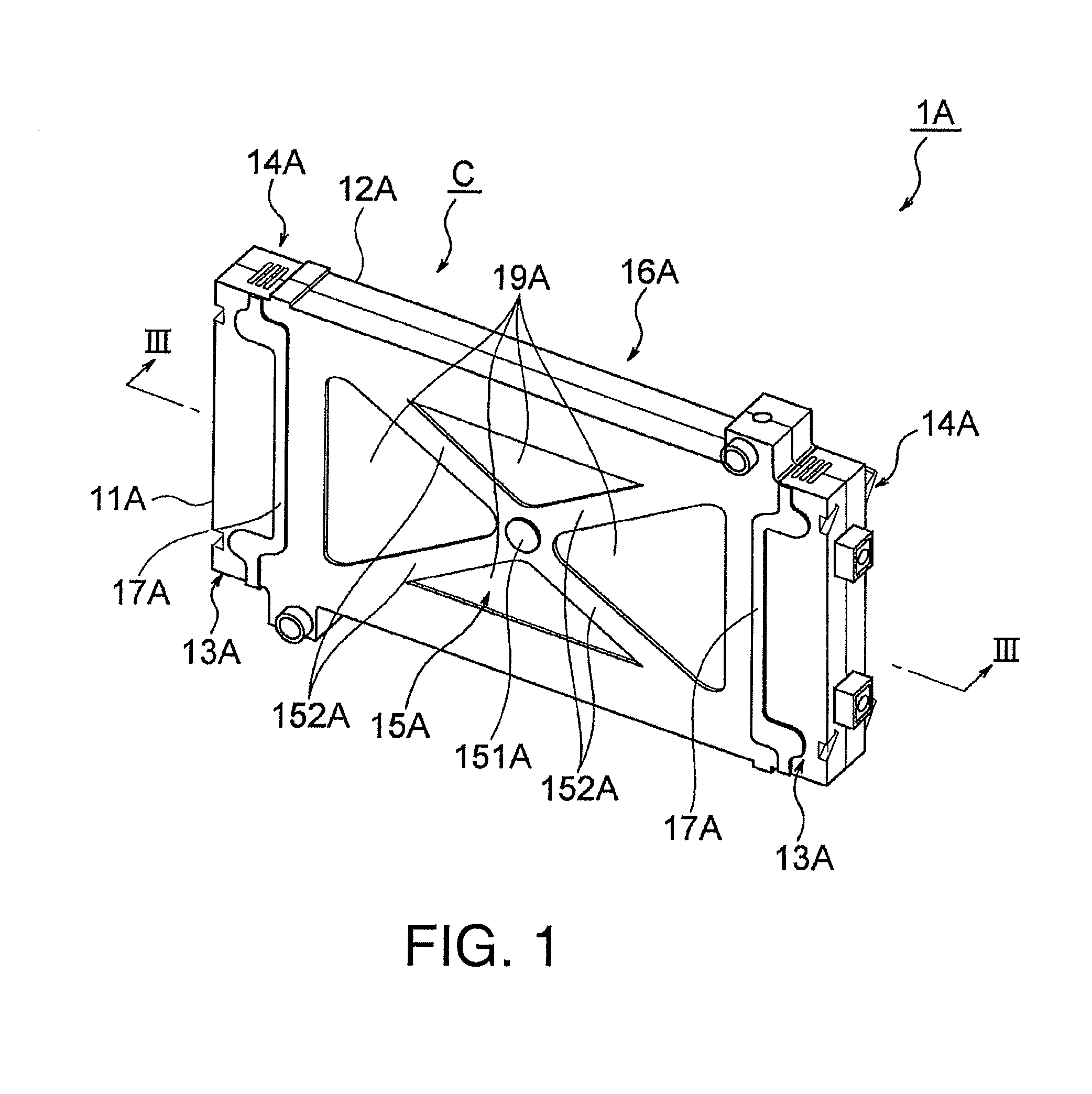
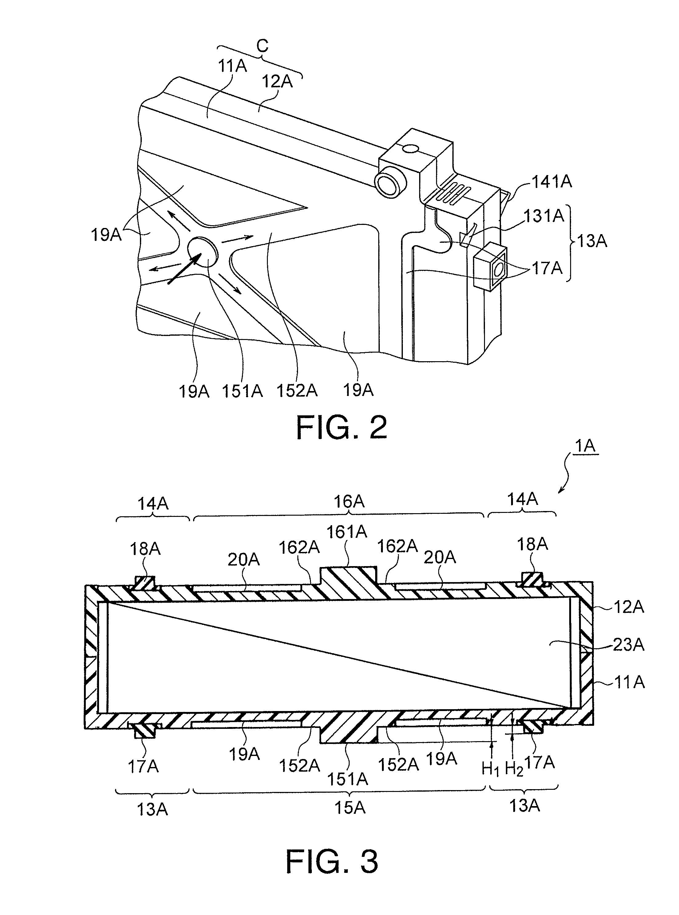
[0021]Referring initially to FIGS. 1 to 3, a single battery module 1A is illustrated in accordance with a FIG. 1 is a perspective view of the single battery module 1A. FIG. 2 is an enlarged partial perspective view of a corner portion of the battery module 1A illustrated in FIG. 1. FIG. 3 is a longitudinal cross sectional view of the battery module 1A illustrated in FIG. 1 as seen along the section line of FIG. 1.

[0022]In this embodiment, as seen in FIG. 4, the battery module 1A is stacked with additional battery modules 1B to 1H, 1J, 1K, 1X and 1Y that are stacked on one another to form a battery module cluster or assembly 1M. The battery modules 1A to 1H, 1J, 1K, 1X and 1Y have main faces that are overlapping in a battery module stacking direction as shown in FIG. 4. In this embodiment, the battery module cluster 1M includes twelve battery modules. However, more or fewer battery modules can be used to form a battery module cluster as needed and / or desired. The battery module clus...

second embodiment

[0056]In this second embodiment, the first protruding flow guides 21 and the second protruding flow guides 22 protrude into the spaces S so as to face one another. Cooling air introduced into the spaces S collides with the first protruding flow guides 21 and the second protruding flow guides 22 such that the flow is organized into zigzagging paths. As a result, the surface area contacted by the cooling air is increased and the cooling effect is increased.

[0057]Referring now to FIG. 10, a battery module in accordance with a third embodiment will now be explained. In view of the similarity between the prior embodiments and this third embodiment, the parts of the third embodiment that are identical to the parts of the prior embodiments will be given the same reference numerals as the parts of the prior embodiments. Moreover, the descriptions of the parts of the third embodiment that are identical to the parts of the prior embodiments may be omitted for the sake of brevity. FIG. 10 is a...


PUM

PropertyMeasurementUnit
elasticaaaaaaaaaa
heightaaaaaaaaaa
surface pressureaaaaaaaaaa

Abstract

A battery module is provided with a battery cell and a case. The case houses the battery cell. The case includes a first main face, a second main face, a first battery module coupling structure and a first elastically deforming structure. The first battery module coupling structure is arranged and configured to retain a first additional battery module over the first main face. The first elastically deforming structure is arranged and configured with respect to the first main face to elastically deform inward towards the second main face upon stacking the first additional battery module onto the first main face while the first additional battery module is retained to the first main face of the case by the first battery module coupling structure.

Description

CROSS-REFERENCE TO RELATED APPLICATIONS[0001]This application is a U.S. National stage of International Application No. PCT / IB2010 / 002080, filed Aug. 25, 2010, which claims priority to Japanese Patent Application No. 2009-210059, filed on Sep. 11, 2009. The entire disclosure of Japanese Patent Application No. 2009-210059 is hereby incorporated herein by reference.BACKGROUND[0002]1. Field of the Invention[0003]The present invention generally relates to a battery module. More specifically, the present invention relates to battery modules that are stacked on one another.[0004]2. Background Information[0005]Sometimes battery modules are arranged in a stack with end plates provided on both ends of the stack of the battery modules to form a battery module cluster or assembly. The end plates are usually fastened at each of the four corners with a fastener that includes a fastening bolt and a nut arrangement such that a uniform surface pressure is applied to the battery modules. An example ...

Claims


Application Information

Patent Timeline
Patent Type & Authority Patents(United States)
IPC IPC(8): H01M2/10H01M2/02H01M50/20H01M50/202H01M50/204
CPCH01M6/46H01M2/0245H01M10/5059H01M10/5032Y02E60/12H01M2/1077H01M10/5004H01M10/6557H01M10/647H01M10/613B60L1/003B60L58/26B60L50/64Y02T10/70Y02E60/10H01M50/258H01M50/20H01M50/204H01M50/202H01M50/10
Inventor MOTOHASHI, TOSHIYUKI
Owner ENVISION AESC JAPAN LTD
Why Eureka
Try Eureka