

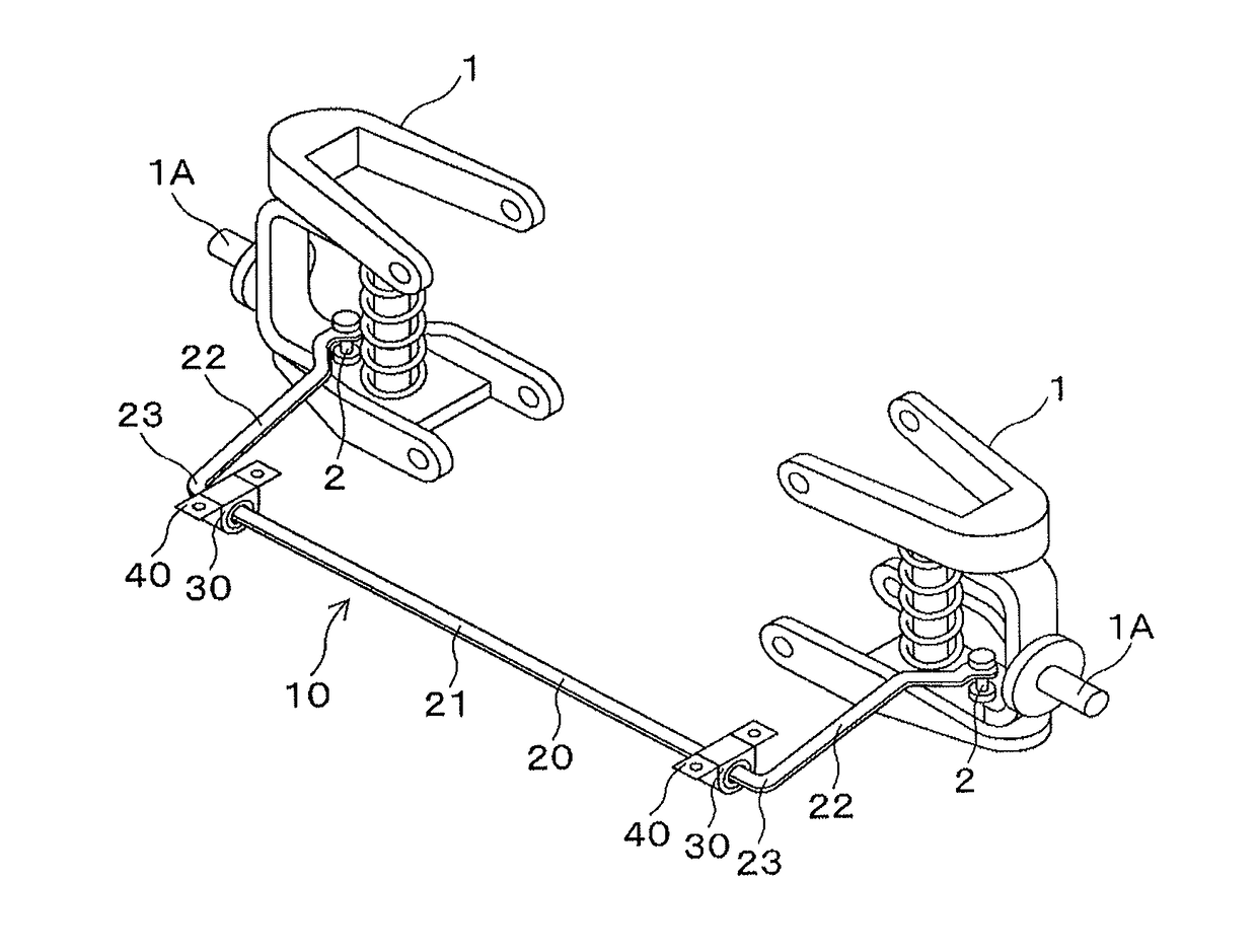
Bush for stabilizer, fastening tool, and fastening method
a stabilizer and tool technology, applied in the direction of mechanical equipment, torsion springs, transportation and packaging, etc., can solve the problems of mud and water entering the gap, noise may be generated, interference with a part other than the torsion part,
- Summary
- Abstract
- Description
- Claims
- Application Information
AI Technical Summary
Benefits of technology
Problems solved by technology
Method used
Image

Examples
first embodiment
(1) First Embodiment
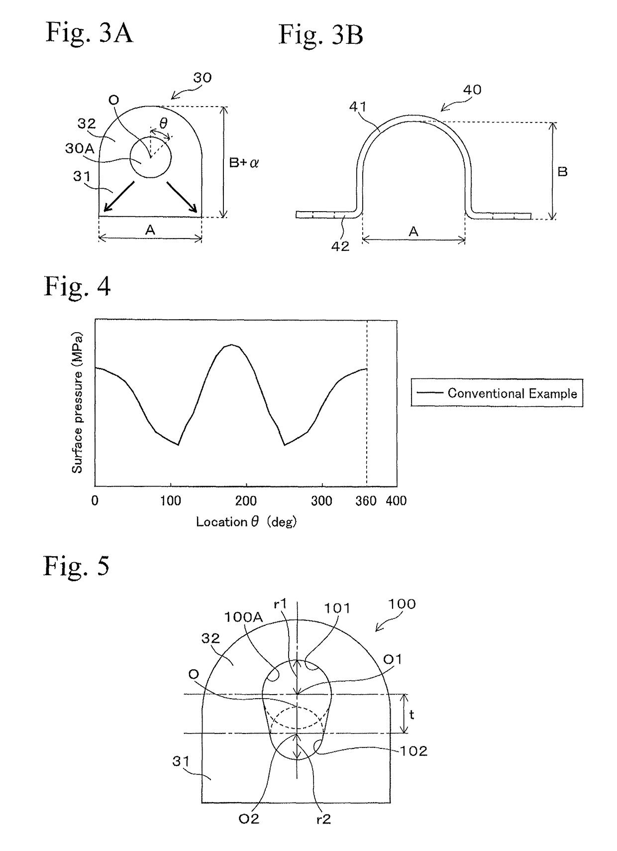
[0043]FIGS. 5 and 6 are cross sectional views showing structures of the bush of the first embodiment according to the present invention (the first aspect of the invention). The bush 100 has a similar structure as the bush 30 shown in FIG. 3A, except that the shape of the hole part is different. Practically, the bush 100 is made of an elastic material such as rubber, and in the bush 100, for example, the length A in the horizontal direction, the length (B+α) in the vertical direction, and the shape of the outer circumferential part are similar to those of the bush 30 shown in FIG. 3A.
[0044]The hole part 100A of the bush 100 includes the first arc part 101, which is formed at the upside, and the second arc part 102 which is formed at the downside. The first arc part 101 and the second arc part 102 are a circular arc part being circular or approximately circular, or an ellipse arc part being an ellipse or approximately an ellipse. It is desirable that the second arc...
second embodiment
(2) Second Embodiment
[0054]FIGS. 9A and 9B are cross sectional views showing the structure of the bush of the second embodiment according to the present invention (the second aspect of the invention). The bush 200 includes the elastic part 201 consisting of an elastic material such as a rubber and the rigid part 202 having a higher degree of rigidity than that of the elastic part 201. The rigid part 202 consists of a metallic part, resin part or the like, for example. The hole part 200A of the bush 200 is formed as an ellipse. The longer axis of the ellipse is located in the vertical direction for example, and the shorter axis of the ellipse is located in the horizontal direction, for example. The rigid part 202 is arranged at the lower side of the center O of the hole part 200A.
[0055]In the bush 200 of the FIG. 9A for example, the upper surface of the rigid part 202 includes a concave part which is formed in a semicircle in cross section, the elastic part 201 is formed so as to be ...
third embodiment
(3) Third Embodiment
[0060]FIG. 11 shows the structure of the bonding tool of the third embodiment according to the present invention (the third and fourth aspects of the invention), and shows the cross sectional view showing the bonding tool in a condition in which the bush for a stabilizer is contained. The bonding tool 300 includes the bush containing part 301 and the plate part 302. The bush containing part 301 is formed in a shape corresponding to the bracket 40, and has a shape similar to that of the bracket 40 except that the excess part for fastening β is arranged in the horizontal direction (in a direction perpendicular to the concave direction of the concave part of the bush containing part 301).
[0061]The bush containing part 301 includes the concave part having a cross section in the shape of the letter U and contains the bush 30 shown in FIG. 3A, for example. The flange parts are formed at both end parts of the concave part of the bush containing part 301 so as to extend ...
PUM
 Abstract
Description
Claims
Application Information