Electrosurgical instrument and jaw part for same

A technology for electrosurgical instruments and instruments, which is applied in the fields of heating surgical instruments, parts of surgical instruments, medical science, etc., can solve the problems of insufficient application, no longer ensuring electrode distance, clamp deflection, etc., and achieves the reduction of coagulation shadows. The effect of forming and reducing the risk of short circuit

Inactive Publication Date: 2017-02-22
AESCULAP AG
View PDF9 Cites 3 Cited by
  • Summary
  • Abstract
  • Description
  • Claims
  • Application Information

AI Technical Summary

Problems solved by technology

However, when a considerable number of spacers are provided on the clamp, as shown in EP 1 656 901 B1, EP 1 952 777 A1, EP 1 372 507 A1 or US 2004 / 122423 A1, the spacers necessarily penetrate Treated tissue because when the clamps are closed, the tissue is compressed under the spacer such that the tissue is permanently damaged
This will affect the result of sealing
[0008] Angular deflection of the jaws will result when the clamp pressure is reduced to avoid tissue perforation and the tissue is only clamped under the spacer
[0009] Since the spacer is also made of non-conductive material in order to avoid short circuits between the HF electrodes, a so-called coagulation shadow will form in the area of ​​said spacer, i.e. tissue parts are enclosed in or below the area of ​​the spacer, so the current Not or only insufficiently applied to the tissue portion, and the vascular portion is not satisfactorily welded there
Furthermore, it has been found that when these non-conductive spacers are secured to the electrodes, for example by gluing, they can easily come off and then possibly enter the patient's body undetected
Furthermore, the predefined electrode distances are no longer guaranteed in this case

Method used


Image

  • Electrosurgical instrument and jaw part for same
  • Electrosurgical instrument and jaw part for same
  • Electrosurgical instrument and jaw part for same

Examples


Embodiment Construction

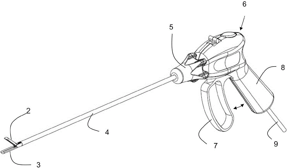
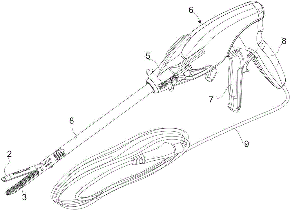
[0048] figure 1 Shows a perspective view of a laparoscopic electrosurgical instrument 1 according to a first embodiment of the invention, said electrosurgical instrument comprising a jaw portion consisting of a pair of instrument branches 2 and 3, preferably in the open The positions are movable towards each other in a scissors-like or pliers-like manner, which are arranged at the distal end of the instrument shaft 4 , which in turn is rotatably fastened to the handle part or handle part 6 by means of manually operable shaft rotation means 5 . Via the shaft rotation device 5 , the shaft 4 and the instrument branches 2 and 3 arranged thereon can be rotated about the longitudinal axis relative to the handle part 6 . The handle portion 6 includes a manually operable handle or trigger 7 which is pivotally movable relative to a handle or pistol grip 8 closely connected to the handle portion 6 . The instrument branches 2 , 3 or at least one manually operable instrument branch 3 are...


PUM


Abstract

An electrosurgical instrument is disclosed having a jaw part composed of instrument branches which are movable towards each other and on each mutually facing side of which one or more electrode surfaces are arranged/formed, wherein the movement of the instrument branches relative to each other can be limited by at least one proximal spacer acting on proximal end portions of the instrument branches, at least one medial spacer acting on a medial portion, and at least one distal spacer acting on distal end portions of the instrument branches. According to the invention, the proximal and/or the distal spacer are made of electrically non-conductive material and the at least one medial spacer is composed of at least one electrode made of an electrically conductive material and connected electrically conductively to the electrode. Furthermore, the at least one medial spacer interacts with a local insulation component made of a non-conductive material, which insulation component is arranged in an electrically insulating manner on at least one opposite electrode.

Description

technical field [0001] The present invention relates to an electrosurgical instrument, in particular an electrosurgical instrument for laparoscopic surgery, comprising a jaw portion consisting of instrument branches movable towards each other and where they face each other One or more electrode surfaces are arranged / formed on the side of the instrument branch, wherein the movement of the instrument branches relative to each other is effected by a proximal spacer acting on the proximal part of the instrument branch, a distal spacer acting on the distal part of the instrument branch and The restriction of at least one intermediate spacer acting on the intermediate portion of the instrument branch. Background technique [0002] After surgical removal of a hollow vessel part, eg during bowel resection due to a part of the bowel being affected by a tumor, the two hollow vessel incisions must be reconnected at their open ends so that a continuous course is formed. This is called ...

Claims


Application Information

Patent Timeline
Patent Type & Authority Applications(China)
IPC IPC(8): A61B18/14
CPCA61B18/1442A61B2018/00494A61B2018/00083A61B18/1445A61B2090/034A61B17/1114A61B2018/00601A61B2018/0063
Inventor 克里斯托夫·罗斯韦勒欧根·赫纳克里斯汀·休伯
Owner AESCULAP AG
Why Eureka
Try Eureka