Integrated near-to-eye display module

a display module and near-to-eye technology, applied in optics, instruments, electrical equipment, etc., can solve the problems of many limited applications of these devices

Active Publication Date: 2014-04-22
GOOGLE LLC
View PDF5 Cites 90 Cited by
  • Summary
  • Abstract
  • Description
  • Claims
  • Application Information

AI Technical Summary

Problems solved by technology

There is certain to be new found practical and leisure applications as the technology evolves; however, many of these applications a...

Method used


Image

  • Integrated near-to-eye display module
  • Integrated near-to-eye display module
  • Integrated near-to-eye display module

Examples


Embodiment Construction

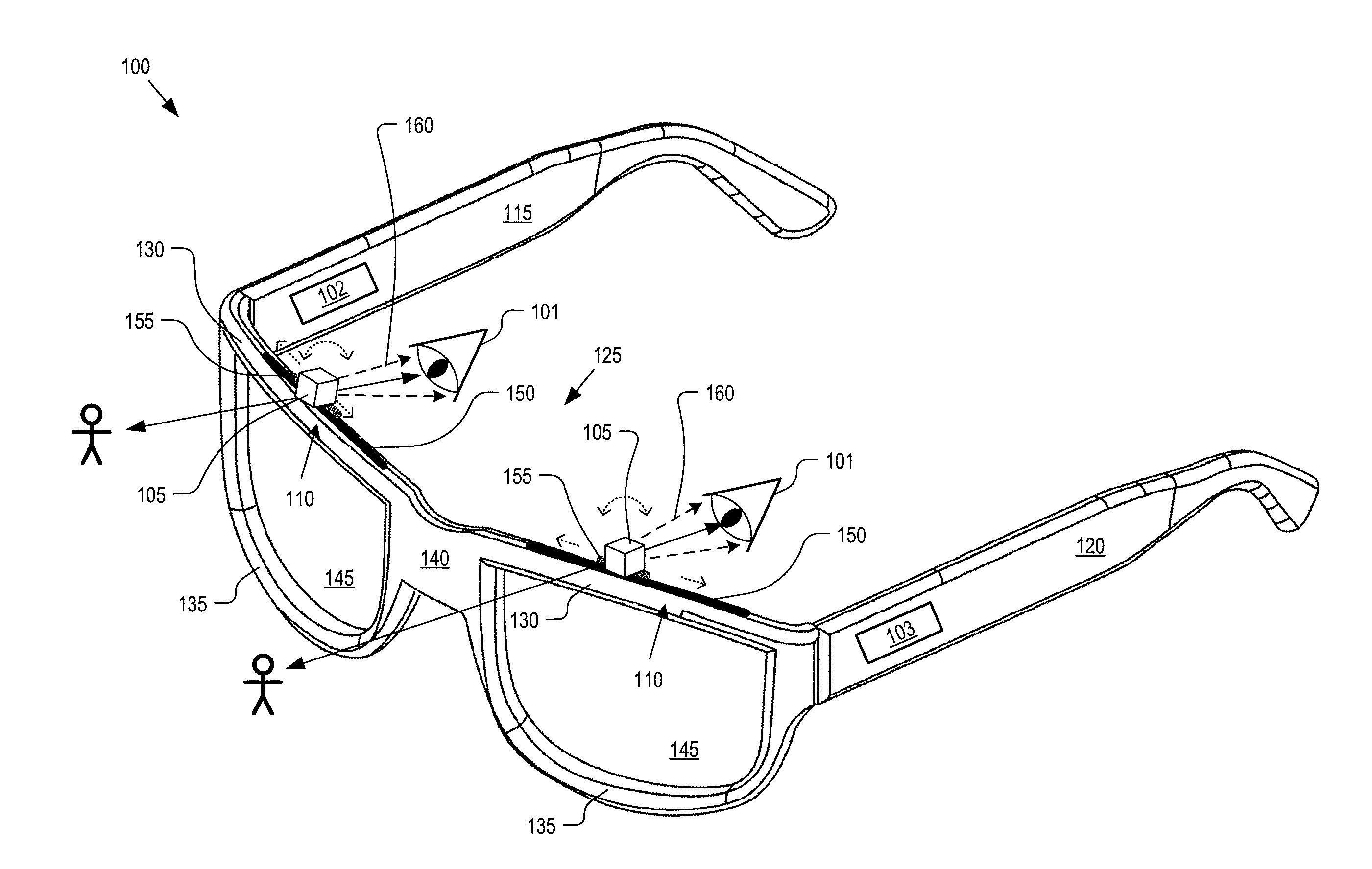
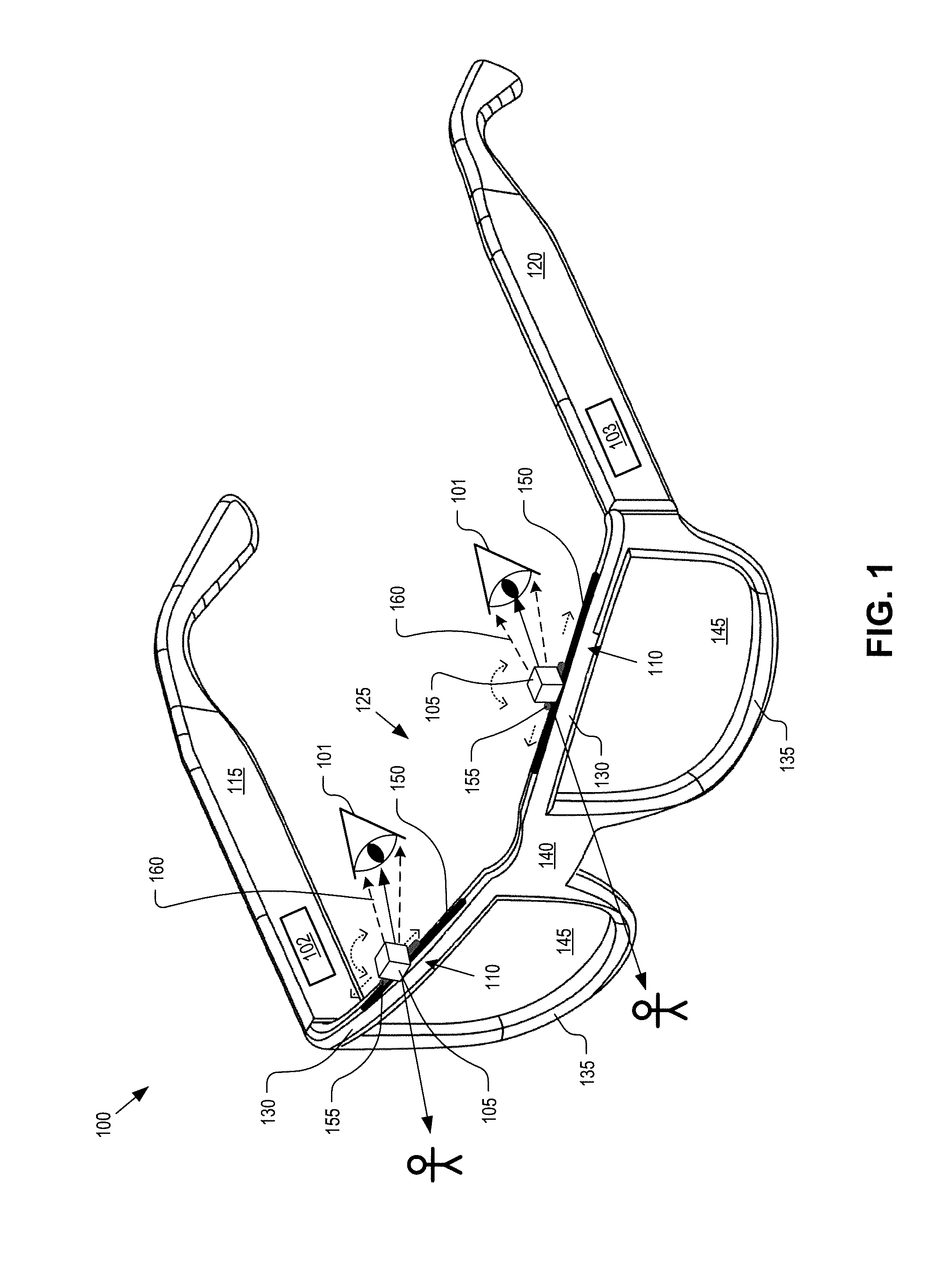
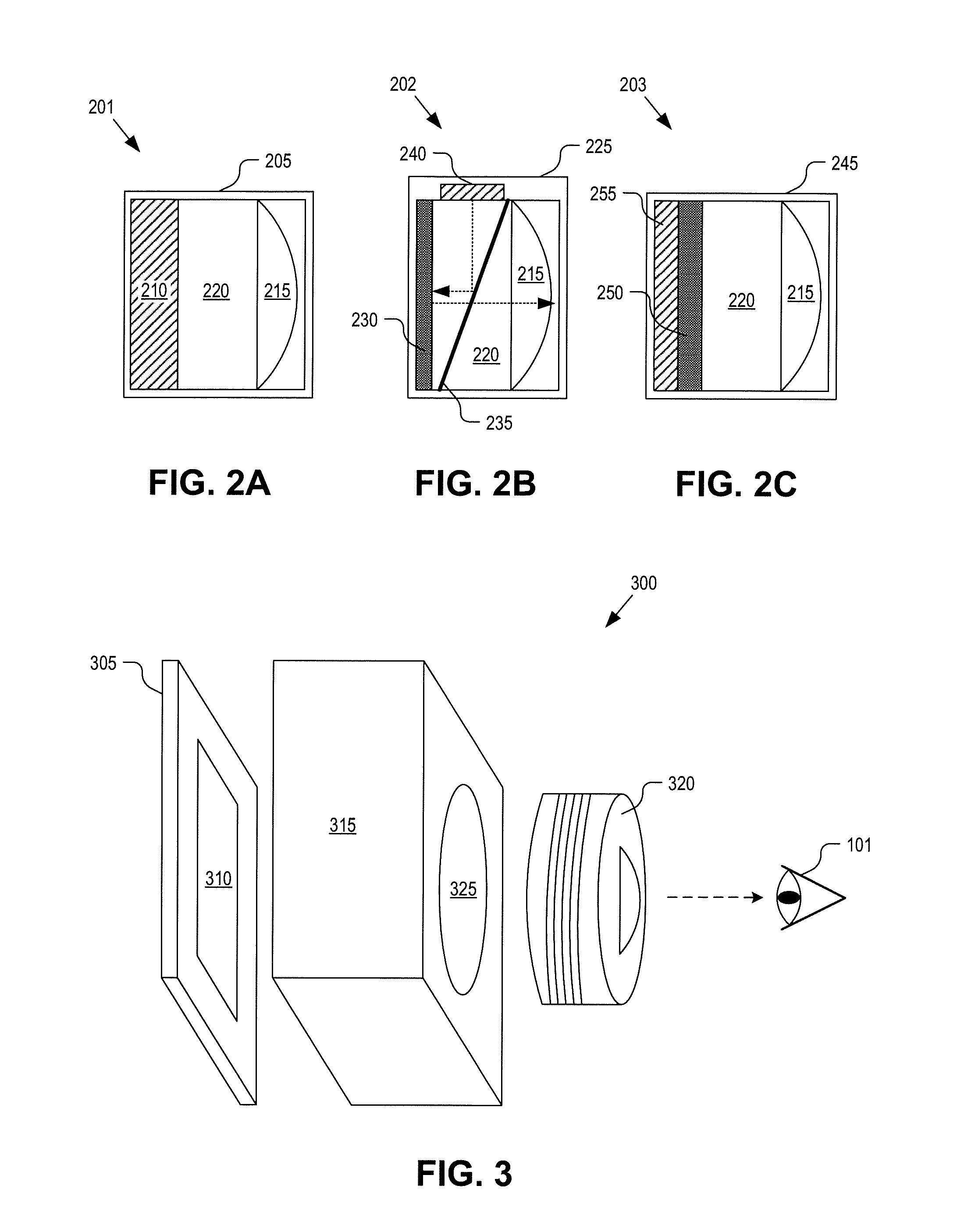
[0014]Embodiments of a method for operating, and apparatus for implementing, a head mounted display (“HMD”) with an integrated near-to-eye display module are described herein. In the following description numerous specific details are set forth to provide a thorough understanding of the embodiments. One skilled in the relevant art will recognize, however, that the techniques described herein can be practiced without one or more of the specific details, or with other methods, components, materials, etc. In other instances, well-known structures, materials, or operations are not shown or described in detail to avoid obscuring certain aspects.

[0015]Reference throughout this specification to “one embodiment” or “an embodiment” means that a particular feature, structure, or characteristic described in connection with the embodiment is included in at least one embodiment of the present invention. Thus, the appearances of the phrases “in one embodiment” or “in an embodiment” in various pla...


PUM


Abstract

A head mounted display (“HMD”) includes a frame assembly for wearing on a head of a user and an integrated display module mounted to the frame assembly within a peripheral viewing region of an eye of the user when the HMD is worn by the user. The integrated display module includes a display source for outputting a computer generated image (“CGI”), a lens system optically aligned with the display source to focus the CGI emitted from the integrated display module towards the eye, and an actuator coupled to adjust a focal distance of the lens system for changing an image depth of the CGI displayed to the user.

Description

TECHNICAL FIELD[0001]This disclosure relates generally to the field of optics, and in particular but not exclusively, relates to near-to-eye optical systems.BACKGROUND INFORMATION[0002]A head mounted display (“HMD”) is a display device worn on or about the head. HMDs usually incorporate some sort of near-to-eye optical system to emit a light image within a few centimeters of the human eye. Single eye displays are referred to as monocular HMDs while dual eye displays are referred to as binocular HMDs. Some HMDs display only a computer generated image (“CGI”), while other types of HMDs are capable of superimposing CGI over a real-world view. This latter type of HMD can serve as the hardware platform for realizing augmented reality. With augmented reality the viewer's image of the world is augmented with an overlaying CGI, also referred to as a heads-up display (“HUD”).[0003]HMDs have numerous practical and leisure applications. Aerospace applications permit a pilot to see vital flight...

Claims


Application Information

Patent Timeline
IPC IPC(8): G02B27/14G03H1/02G09G5/00H04N13/395
CPCG02B2027/0154G09G5/00G02B2027/0127G09G2300/023G02B27/0172G09G2300/0452G09G3/003G02B2027/0178G09G3/3225G03H1/02H04N13/395
Inventor MIAO, XIAOYU
Owner GOOGLE LLC
Why Eureka
Try Eureka