Device and method for receiving RF signals based on heterodyne architecture using complex IF subsampling

a heterodyne architecture and heterodyne technology, applied in the field of rf receivers with sampled architectures, to achieve the effect of fewer losses in filtered signals and less sensitivity

Inactive Publication Date: 2014-04-22
COMMISSARIAT A LENERGIE ATOMIQUE ET AUX ENERGIES ALTERNATIVES
View PDF13 Cites 4 Cited by
  • Summary
  • Abstract
  • Description
  • Claims
  • Application Information

AI Technical Summary

Benefits of technology

[0025]The invention therefore provides an RF reception device including a voltage sampling architecture which does not require the generation of signals of high frequencies, thus enabling the reception device according to the invention to have a low electrical consumption (for example allowing a gain of approximately 30% to be obtained compared to the devices of the prior art).
[0031]Through a first frequency transposition of the RF signal to frequency IF1, the useful band of the signal to be sampled is reduced from BWRF, corresponding to the total bandwidth of the RF signal, to BWch, corresponding to the bandwidth of the channel of interest of the received signal, allowing the signal to be transposed to a frequency IF2 which is notably lower than in the receivers of the prior art, without however causing aliasing.
[0032]By accomplishing a complex bandpass filtering centred on frequency IF2=α·fs / M+fs / (M·n), the discrete-time filtering function of the reception device is used optimally, since such filtering enables the image filtering and anti-aliasing rejections required with a filtering of a lower order than the one required in the architectures of the prior art to be achieved. Consequently, when these second filtering means are produced from switched capacitors, such a filter can be produced from a smaller number of switched capacitors than for the intermediate filters of the architectures of the prior art, thus causing fewer losses in the filtered signals, and having a lesser sensitivity to the technological variations relating to the production of the elements of the receiver device.
[0035]The second filtering means may include at least one infinite impulse response (IIR) filter. Such an IIR filter has a response which is much more selective than that of a finite impulse response (FIR) filter of the same order centred on a given frequency. Such a filter notably enables the constraints relating to the analog-digital conversion means to be lessened appreciably. This filter may be produced, for example, from four switched capacitors. This filter not only enables image frequencies and aliasing to be eliminated, but also enables channel filtering of the useful signal in order to eliminate the adjacent channels.

Problems solved by technology

In addition, since the system's thermal noise is broadband, this noise is aliased in the baseband.
However, if the useful signal centred on fc exceeds the order of magnitude of sampling frequency fs, the implemented filtering function then begins to reject the signal of interest.
And, given that the electrical consumption of the receiver circuit is dependent on the highest frequency generated in the circuit (where the elements generating these high frequencies can account for nearly 40% of the total electrical consumption of the receiving device), such architecture does not therefore enable the receiver's electrical consumption to be reduced significantly.
In addition, when the signal is sent in the baseband, the properties of the analog components relative to the non-linearities and to the noise forms an important source of distortions of the signal (for example: 1 / f noise, offset DC, second-order non-linearities).
In addition, when the signal is reduced to a zero intermediate frequency (“zero-IF”), problems relating to the 1 / f noise and offset DC are then posed.
Finally, there are potentially gain and phase differences between the channels.
However, such a filter has low selectivity, which implies that a second filter operating at an intermediate IF frequency higher than twice the RF bandwidth is used, this frequency being higher the greater the signal's RF bandwidth, in order to prevent any aliasing during sampling.
Given that, in this architecture, the sampling frequency is defined by the relationship fs=4·1F in order to accomplish a separation of the in-phase and quadrature paths of the IF signal, and to accomplish image filtering, a relatively high sampling frequency is therefore found in this case too, which does not allow a significant reduction of the receiver's electrical consumption.
In addition, in order to attain the required rejection, such an architecture must use a filtering network in discrete time including a substantial filtering order (24 in this document), which leads to area and electrical consumption constraints for this type of reception architecture.
It can therefore be seen that the RF reception devices of the prior art accomplishing subsampling of the signal pose several problems:the reference frequencies used (frequency of the sampler, intermediate frequency) are at least equal to frequency fRF / 2 in the case of voltage sampling architectures, and at least equal to frequency fRF in the case of charge sampling architectures, which does not enable the receiver's total electrical consumption to be reduced significantly,in the case of architectures transposing the signal directly in the baseband, the properties of the analog components relative to the non-linearities and to the noise are a major source of distortions of the signal,using discrete-time filtering networks with a high filtering order demands a large area for the accomplishment of such networks, and also represents a source of substantial electrical power consumption.

Method used


Image

  • Device and method for receiving RF signals based on heterodyne architecture using complex IF subsampling
  • Device and method for receiving RF signals based on heterodyne architecture using complex IF subsampling
  • Device and method for receiving RF signals based on heterodyne architecture using complex IF subsampling

Examples


Embodiment Construction

[0068]The present invention will be better understood on reading the description of example embodiments given purely as an indication and in no way restrictively, making reference to the appended illustrations in which:

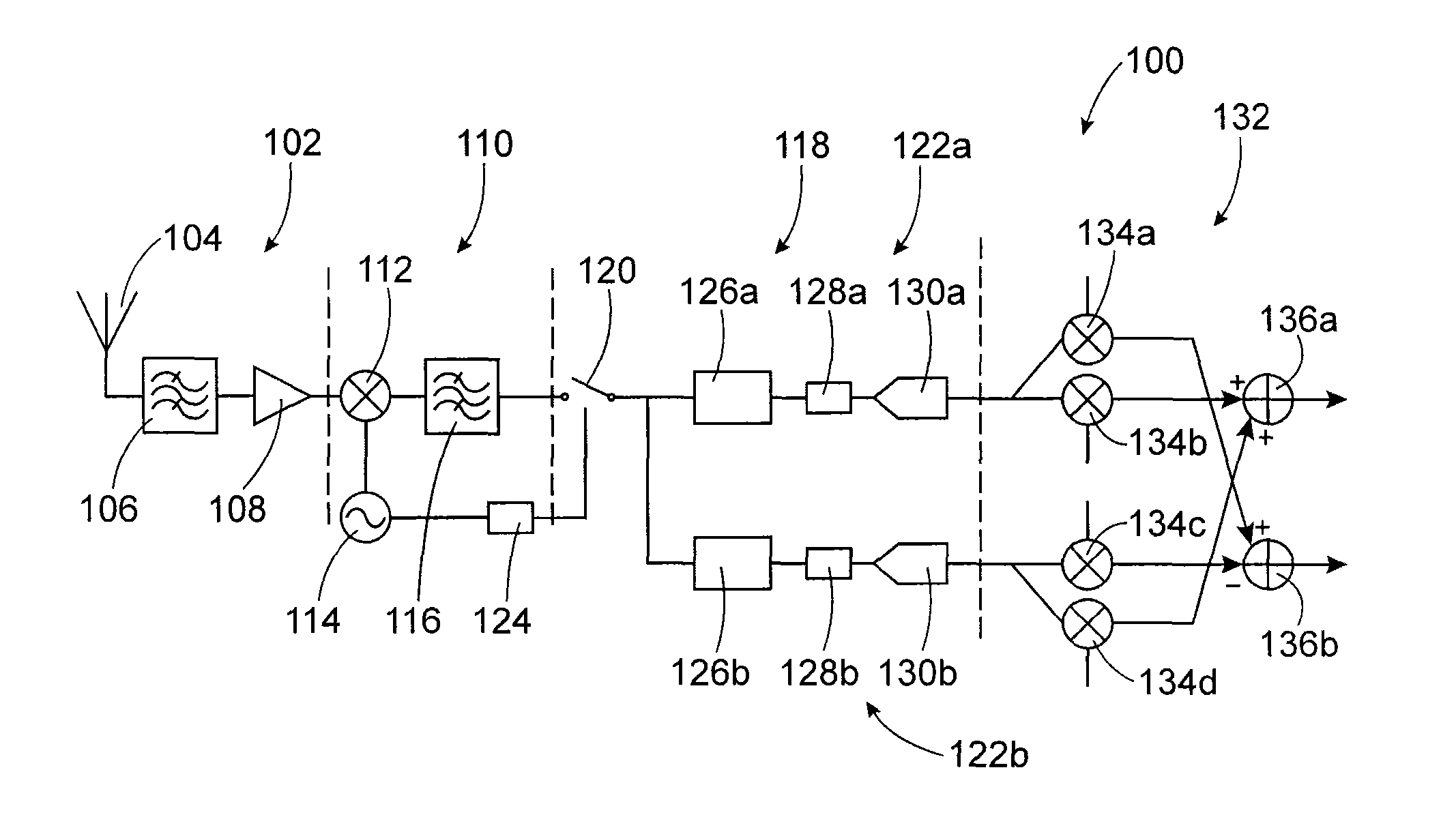
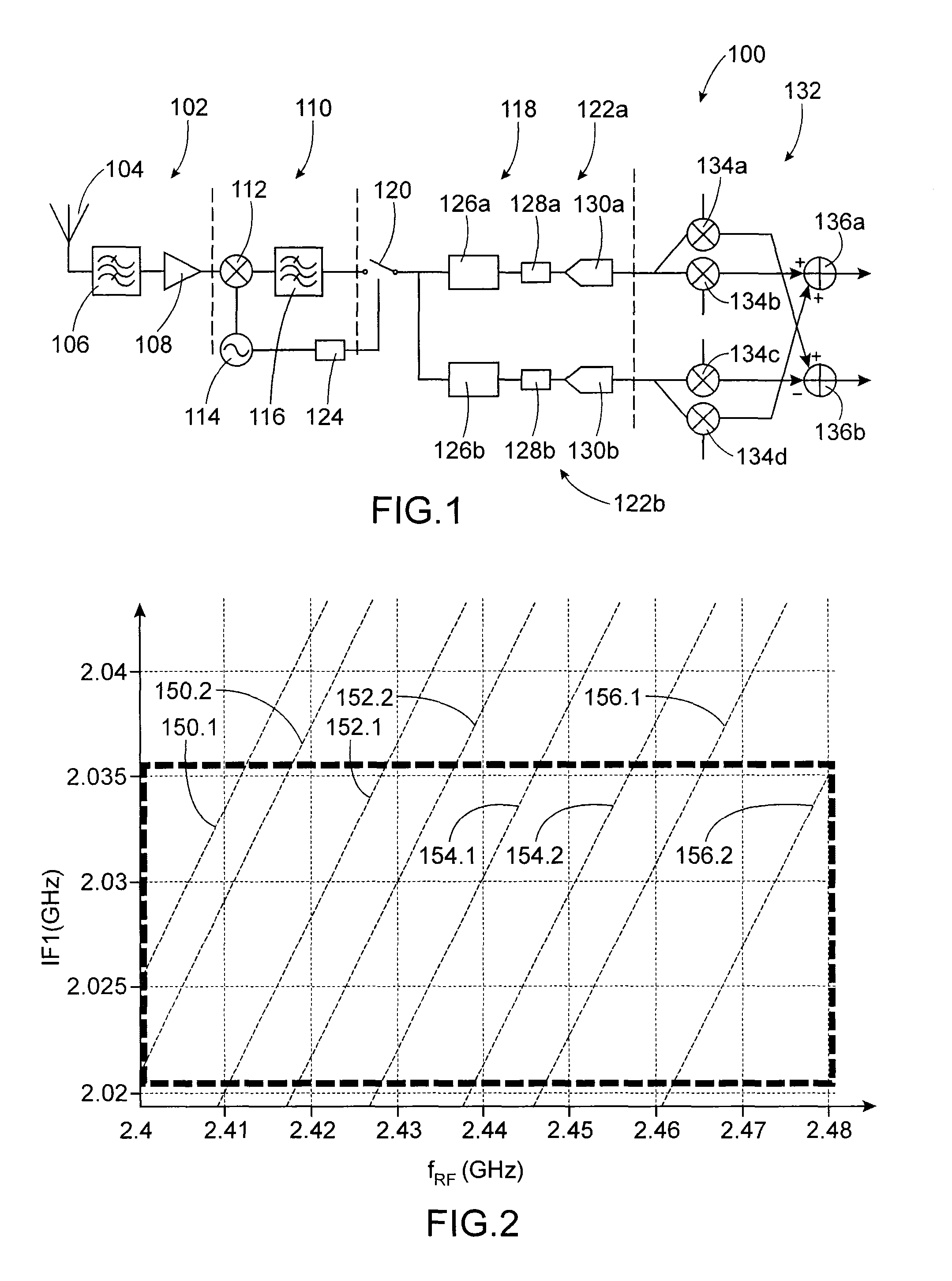
[0069]FIG. 1 represents an RF reception device, object of the present invention, according to a particular embodiment,

[0070]FIG. 2 represents the variations of IF1 as a function of fRF, K and N in an RF reception device, object of the present invention, according to a first example embodiment,

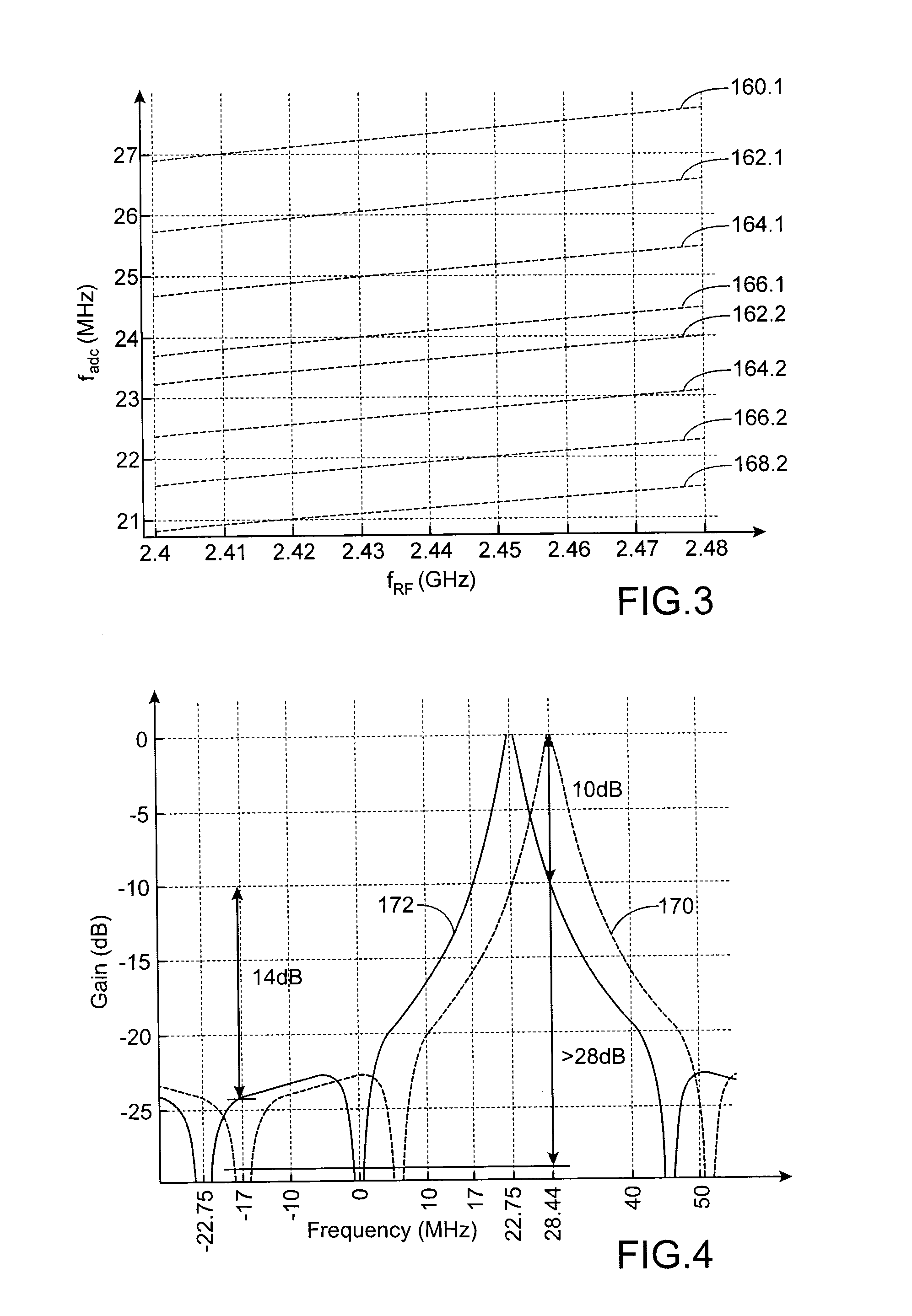
[0071]FIG. 3 represents the variations of fadc as a function of fRF, K and N in the RF reception device, object of the present invention, according to the first example embodiment,

[0072]FIG. 4 represents bandpass filtering functions obtained by IIR filters one of which forms part of the RF reception device, object of the present invention, according to the first example embodiment,

[0073]FIG. 5 represents the variations of IF1 as a function of fRF and K in an RF reception device, ...


PUM


Abstract

An RF signal reception device including: a transposition device of signals of frequency fRF to a first intermediate frequency IF1<fRF; a first bandpass filter centered on IF1; a sampler at a frequency fs<IF1; a second discrete-time filter centered on a second intermediate frequency IF2=α·fs / M+fs / (M·n); a decimation device of a factor M; an analog-digital convertor to operate at a frequency fs / M; where α, n and M are strictly positive real numbers chosen such that: α<fs / (2·BWch·M), and BWch / 2<fs / M·n), with BWch: bandwidth of a channel of the received RF signals.

Description

TECHNICAL FIELD[0001]The invention concerns the field of reception of radio frequency (RF) signals, and more specifically that of RF receivers with sampled architectures.[0002]The invention notably concerns a device and a method for receiving signals according to communication standards such as the “Bluetooth Low Energy”, IEEE 802.15.4 or “ZigBee” standards, for example implemented for applications in wireless personal area networks (WPAN), wireless body area networks (WBAN), notably in the medical field, or again wireless sensor and actuator networks (WS&AN), or any other application having channels with a low bandwidth, for example less than 4 MHz. The invention can notably be used in communicating devices with a high dynamic range having compatibility between several standards (multi-standard data reception).STATE OF THE PRIOR ART[0003]In RF receivers with sampled architectures, the reconfigurable character of these receivers enables multiple communication standards to be demodul...

Claims


Application Information

Patent Timeline
Patent Type & Authority Patents(United States)
IPC IPC(8): H04B1/00
CPCH04B1/0025
Inventor LOLIS, LUISPELISSIER, MICHAEL
Owner COMMISSARIAT A LENERGIE ATOMIQUE ET AUX ENERGIES ALTERNATIVES
Why Eureka
Try Eureka