
Two-phase flow exciting force evaluation method and device acting on a plurality of tube bodies arranged to intersect with the flow

a technology of exciting force and evaluation method, which is applied in the direction of instruments, nuclear elements, greenhouse gas reduction, etc., can solve the problems of troublesome installation difficult to make accurate measurements, and large size of the entire device including the flow path, so as to achieve easy and accurate evaluation of the exciting force acting, simple configuration, and simple configuration

Active Publication Date: 2014-04-29
MITSUBISHI HEAVY IND LTD
View PDF4 Cites 0 Cited by
  • Summary
  • Abstract
  • Description
  • Claims
  • Application Information

AI Technical Summary

Benefits of technology

The present invention provides a method and device to easily and accurately evaluate the exciting force acting from two-phase flow on a tube body. This is accomplished by measuring the void fraction of the two-phase flow and measuring displacement or stress of the tube body, using one of the tube bodies to be vibrated. This method and device have a simple configuration and can provide valuable information for the analysis and design of flow excitation systems.

Problems solved by technology

Consequently, there is a problem in that the entire device including the flow path becomes large, and installation thereof is troublesome.
Moreover, since each piece of equipment needs to be installed in different positions, there is a problem in that the measurement result of the measured two-phase flow void fraction and the measurement result of the vibration of the corresponding pipe line need to be synchronized, and it is difficult to make accurate measurements and measurement is time consuming.

Method used


Image

  • Two-phase flow exciting force evaluation method and device acting on a plurality of tube bodies arranged to intersect with the flow
  • Two-phase flow exciting force evaluation method and device acting on a plurality of tube bodies arranged to intersect with the flow
  • Two-phase flow exciting force evaluation method and device acting on a plurality of tube bodies arranged to intersect with the flow

Examples


first embodiment

(First Embodiment)

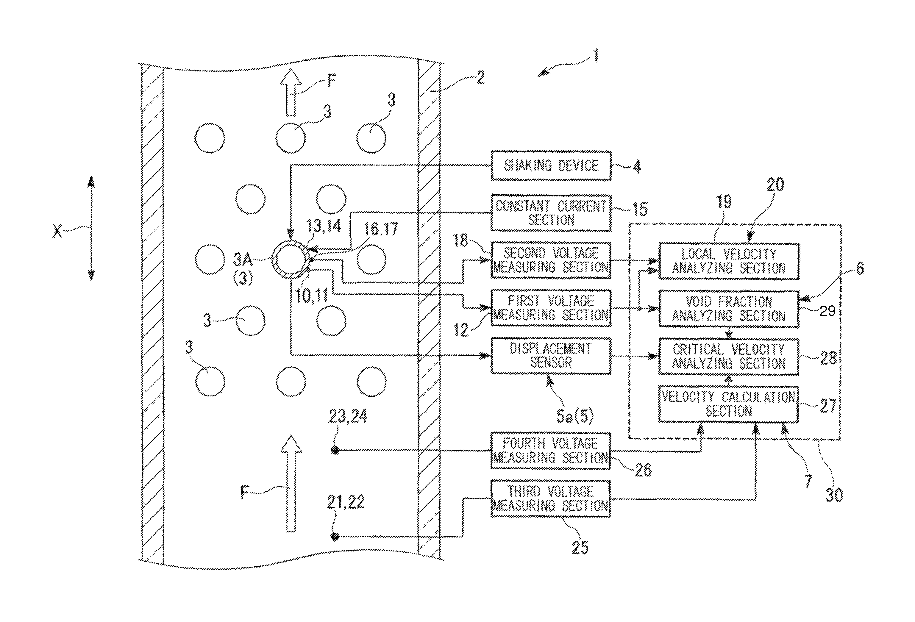
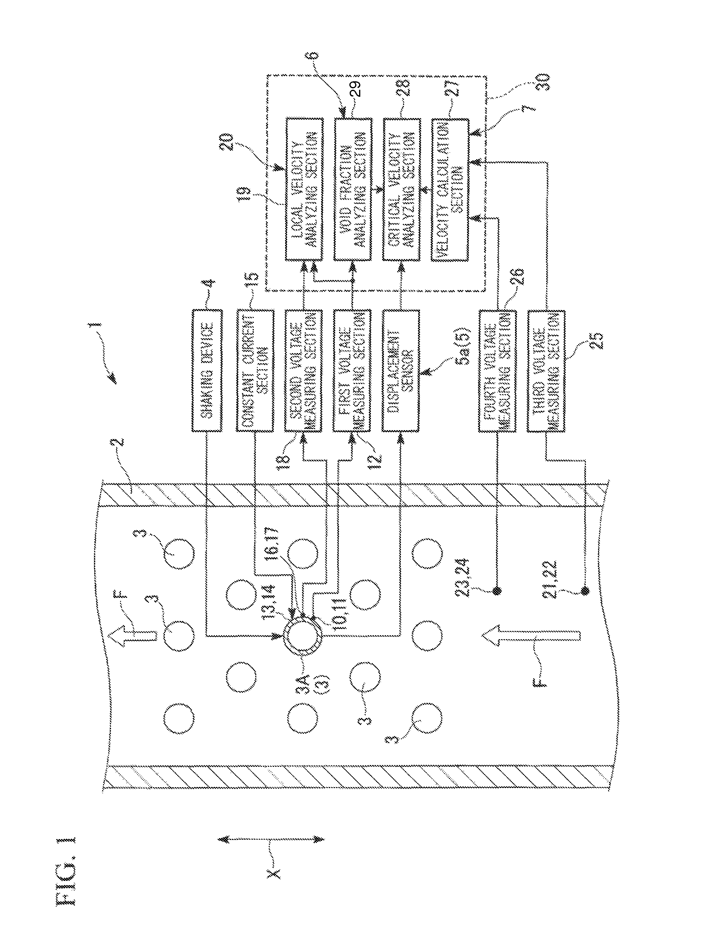
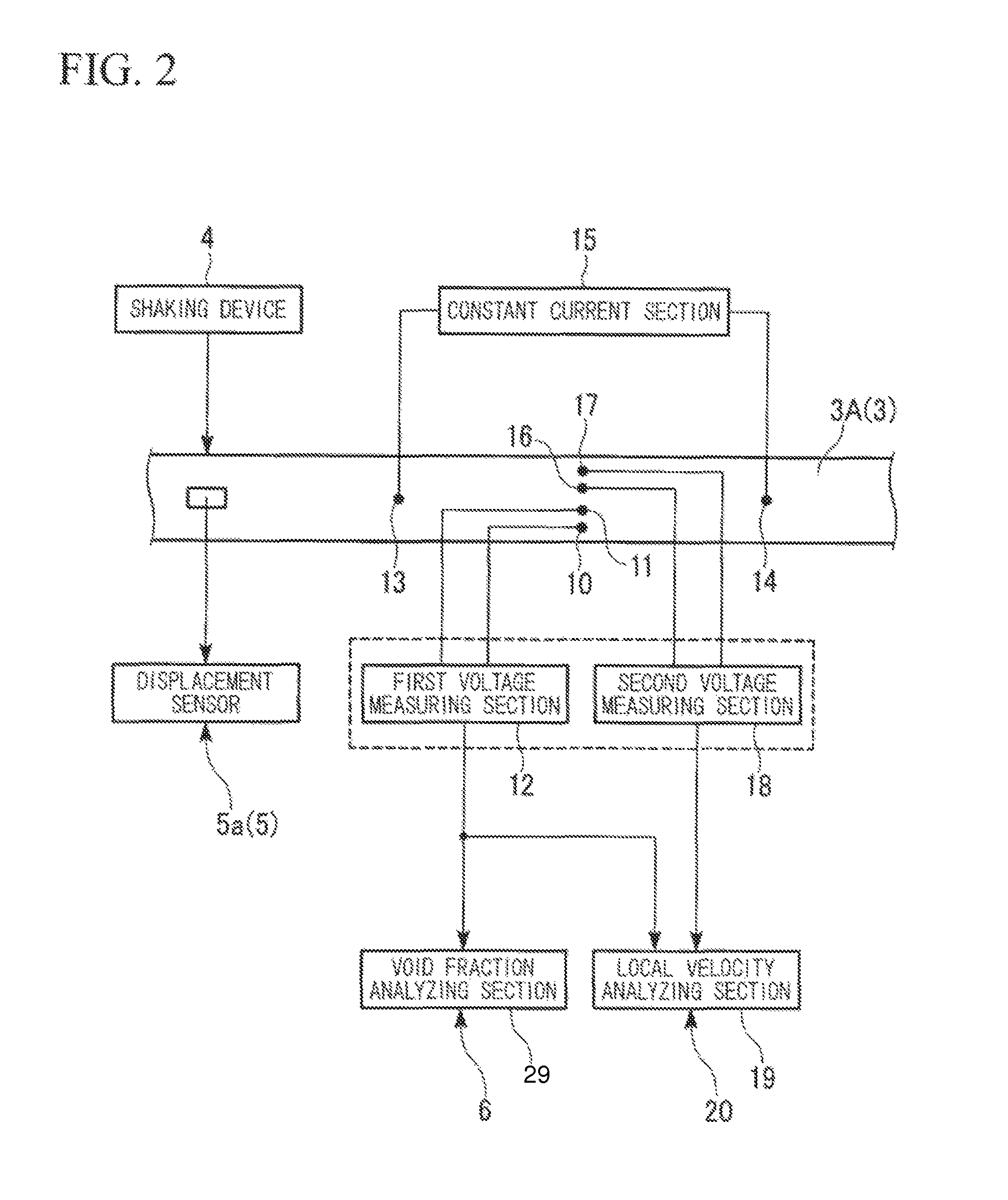
[0032]Hereunder, a first embodiment of the present invention is described, with reference to FIG. 1 through FIG. 4.

[0033]As shown in FIG. 1 and FIG. 2, a two-phase flow exciting force evaluation device 1 of the present embodiment is provided with; a flow section 2 that passes therethrough a two-phase flow F taken as a model flow, a plurality of tube bodies 3 arranged inside the flow section 2 so as to orthogonally intersect with a flow direction X of the two-phase flow F, a shaking device 4 that vibrates the tube bodies 3, an exciting force evaluation device 5 that measures displacement of the tube bodies 3 that are vibrating, a void fraction measuring device 6 that measures the void fraction of the two-phase flow F, and a two-phase flow velocity measuring device 7 that measures the velocity V of the two-phase flow F.

[0034]The two-phase flow F is a model flow of a secondary coolant which is boiling in an evaporator, and it is composed of an alcohol and a sulfur hex...

second embodiment

(Second Embodiment)

[0043]Next, a second embodiment of the present invention is described. FIG. 5 shows the second embodiment of the present invention. In this embodiment, members which are commonly used in the embodiment described above are given the same reference symbols, and descriptions thereof are omitted.

[0044]As shown in FIG. 5, in a two-phase flow exciting force evaluation device 40 of the present embodiment, a void fraction measuring device 41 has; a first voltage measuring section 43 that measures a potential difference between first electrodes 42 provided on the inner surface of the flow section 2 facing the vibration pipe 3A and the surface of the vibration pipe 3A, and a void fraction analyzing section 29 that calculates a void fraction based on the potential difference detected by the first voltage measuring section 43.

[0045]Also in this type of two-phase flow exciting force evaluation device 40, the Potential difference between the first electrodes 42 and the vibratio...


PUM


Abstract

In a two-phase flow exciting force evaluation method of the present invention, the surface of one of a plurality of tube bodies (3) is at least partially formed from a conductive material, displacement or stress of the tube body (3) is measured in a state of being vibrated by a shaking device (4), and a void fraction of a two-phase flow (F) flowing in the vicinity of the tube body (3) is measured based on the potential difference between an electric potential at a predetermined position on the surface of the tube body (3), and a reference electric potential.

Description

TECHNICAL FIELD[0001]The present invention relates to a two-phase flow exciting force evaluation method and a two-phase flow exciting force evaluation device for evaluating an exciting force which acts on a plurality of tube bodies arranged so as to intersect with the flow of a two-phase flow.[0002]Priority is claimed on Japanese Patent Application No. 2009-121190, filed May 19, 2009, the contents of which are incorporated herein by reference.BACKGROUND ART[0003]For example, in a pressurized light-water reactor or an integrated modular light-water reactor, primary coolant in a pressurized state is circulated between a reactor core and a steam generator, and the heat of the primary coolant is transmitted to secondary coolant by the steam generator, to thereby generate steam. Here, inside the steam generator there are arranged a plurality of pipe lines bent in a U-shape and through which passes the primary coolant which circulates between the reactor core and the steam generator. By f...

Claims


Application Information

Patent Timeline
Patent Type & Authority Patents(United States)
IPC IPC(8): G01F1/20
CPCG01N2291/02836G01N2291/0215G01N2291/2634G21C17/022G01N29/045G21C17/017G21D1/006G01N2291/02433G21C17/10G01N29/032Y02E30/30G21C17/02
Inventor KONDO, YOSHIYUKINISHIDA, KENJI
Owner MITSUBISHI HEAVY IND LTD
Learn More