
Semiconductor substrate evaluating method, semiconductor substrate for evaluation, and semiconductor device

a semiconductor substrate and substrate technology, applied in the direction of individual semiconductor device testing, semiconductor/solid-state device testing/measurement, instruments, etc., can solve the problems of non-uniform insulators, device yield reduction, and inability to judge the effects of devices, etc., to achieve easy and accurate evaluation of leakage current characteristics and high yield

Active Publication Date: 2017-07-04
SHIN-ETSU HANDOTAI CO LTD
View PDF29 Cites 0 Cited by
  • Summary
  • Abstract
  • Description
  • Claims
  • Application Information

AI Technical Summary

Benefits of technology

The invention describes a method to evaluate the leakage current characteristics of high-quality wafers used for the production of semiconductor devices like CCDs and CMOS sensors. The method prevents the measurement of leakage currents from the periphery of the well by using a channel stop layer at the junction of the well. This prevents the influence of surface / interface state factors and reduces the occurrence of parasitic depletion capacitance. The method allows for accurate and easy evaluation of leakage current characteristics, important for ensuring high yield of the final product.

Problems solved by technology

If defects and / or metal impurities are present on the original silicon surface, they are taken into the silicon oxide film due to the thermal oxidation, resulting in a nonuniform insulator.
However, even when no problem occurs in the GOI evaluation, it is naturally possible that device yield is reduced.
However, unless devices such as solid state image sensors are actually manufactured in silicon wafer substrates and evaluated, effects thereof cannot be judged.

Method used


Image

  • Semiconductor substrate evaluating method, semiconductor substrate for evaluation, and semiconductor device
  • Semiconductor substrate evaluating method, semiconductor substrate for evaluation, and semiconductor device
  • Semiconductor substrate evaluating method, semiconductor substrate for evaluation, and semiconductor device

Examples


example 1

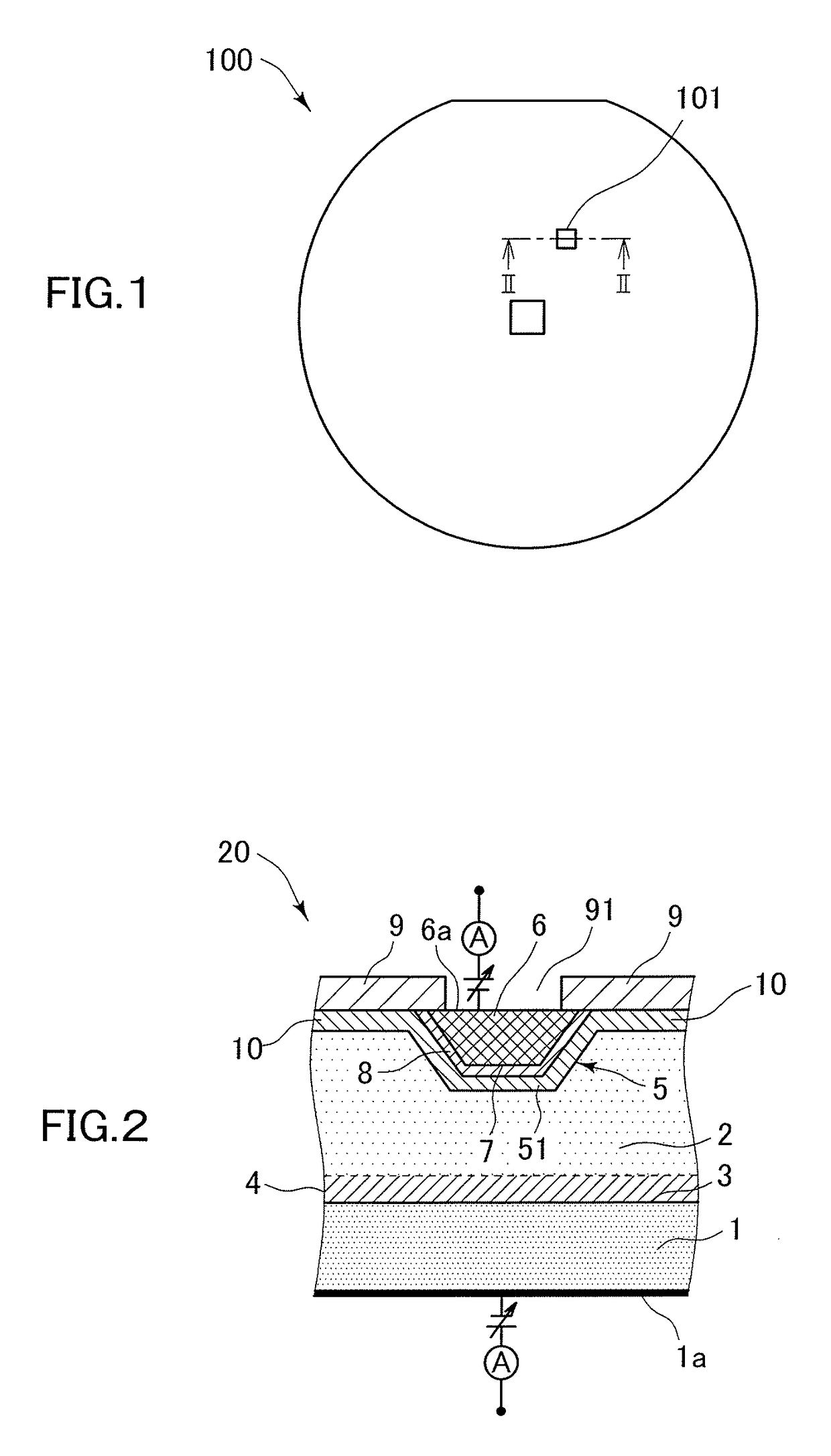
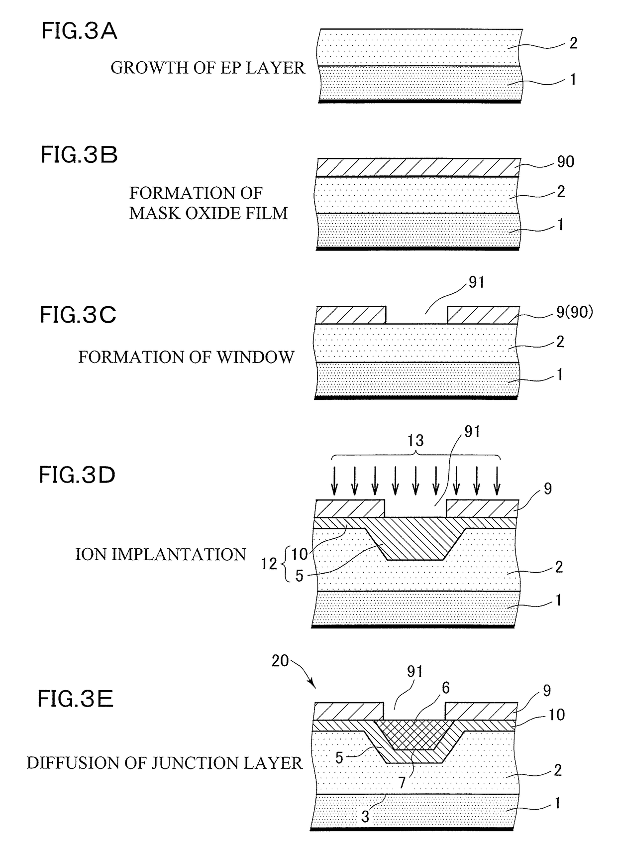
[0046]The following experiment was performed for confirming the effect of this invention. It is noted that this invention is not limited to the following example. A boron-doped silicon wafer having a diameter of 200 mm and a resistivity of 10 Ω·cm (corresponding to the EP substrate 1 shown in FIG. 2) was used as a material. First, the wafer was put in an epitaxial reactor in which presence of heavy metal contamination has already been known, and a phosphorus-doped EP layer was grown thereon. At this time, the EP layer had a thickness of 10 μm, and a resistivity of 10 Ω·cm. This wafer was subjected to a Pyro atmosphere at 1000° C. for 90 minutes to form an oxide film having a thickness of 200 nm thereon. Thereafter, a photoresist was applied, and photolithography was performed. A negative photoresist was selected this time. Apertures of various areas were prepared in the mask so as to enable measurement of area-dependency of junction leakage. In addition, apertures having the same ar...


PUM


Abstract

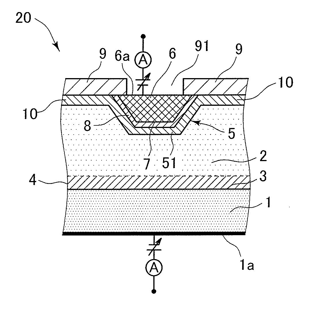
On an EP substrate 1, an EP layer 2 having a conductivity type different from that of the EP substrate 1 is grown. With ion implantation, a well 5 having the same conductivity type as the EP layer 2 is formed, and a channel stop layer 10 is also formed. A dopant having a conductivity type different from that of the well 5 is diffused in the well 5 to form a pn junction 7 in the well 5. A plurality of cells 20 each having the diffusion layer 6 as one electrode and a rear surface 1a as the other electrode are formed as a TEG. Using the TEG, junction leakage currents from two depletion layers, a depletion layer 8 in the well and a depletion layer 4 at an interface between the EP layer 2 and the EP substrate 1, are measured.

Description

CROSS-REFERENCE TO RELATED APPLICATIONS[0001]This present application is a National Stage entry of International Application No. PCT / JP2013 / 062277, filed Apr. 25, 2013, which claims priority to Japanese Patent Application No. 2012-135726, filed Jun. 15, 2012. The disclosures of the prior applications are incorporated in their entirety reference.FIELD OF THE INVENTION[0002]This invention relates to a semiconductor substrate evaluating method, and more particularly, to a method of evaluating electrical characteristics in the vicinity of the surface of a silicon wafer, a semiconductor substrate, and a semiconductor device. In particular, the invention relates to a method of evaluating a junction leakage current of a semiconductor substrate, and a semiconductor substrate and a semiconductor device used for the evaluation method.BACKGROUND OF THE INVENTION[0003]With increasing miniaturization and sophistication of semiconductor devices such as memories, solid state image sensors such as ...

Claims


Application Information

Patent Timeline
Patent Type & Authority Patents(United States)
IPC IPC(8): G01R31/26H01L21/66H01L29/06H01L29/10
CPCG01R31/2601H01L22/34H01L29/0638H01L29/1095H01L22/14H01L2225/06596
Inventor OHTSUKI, TSUYOSHI
Owner SHIN-ETSU HANDOTAI CO LTD
Learn More