Device for measuring a fluid meniscus

a fluid meniscus and geometry technology, applied in the direction of resistance/reactance/impedence, electric/magnetic measuring arrangement, instruments, etc., can solve the problem of impeded determination of single capacitance by the interaction of auxiliary electrodes, and achieve the effect of accurate measurement of geometry

Active Publication Date: 2011-08-25
KONINKLIJKE PHILIPS ELECTRONICS NV
View PDF10 Cites 11 Cited by
  • Summary
  • Abstract
  • Description
  • Claims
  • Application Information

AI Technical Summary

Benefits of technology

[0006]It is an object of the invention to provide a device as described in the preamble for more accurately measuring the geometry of the fluid meniscus. This object is achieved by the device according to the invention, the device comprising a fluid chamber comprising a first fluid and a second fluid, which first fluid is electrically conductive, which second fluid is electrically insulating, and which first and second fluids are mutually immiscible and in contact with each other over a fluid meniscus, a main electrowetting electrode located in a main plane and aux...

Problems solved by technology

The interaction between the auxiliary electrod...

Method used


Image

  • Device for measuring a fluid meniscus
  • Device for measuring a fluid meniscus
  • Device for measuring a fluid meniscus

Examples


first embodiment

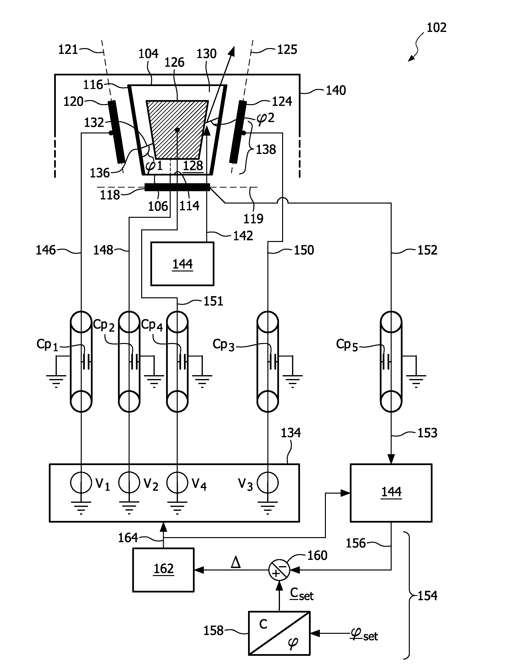
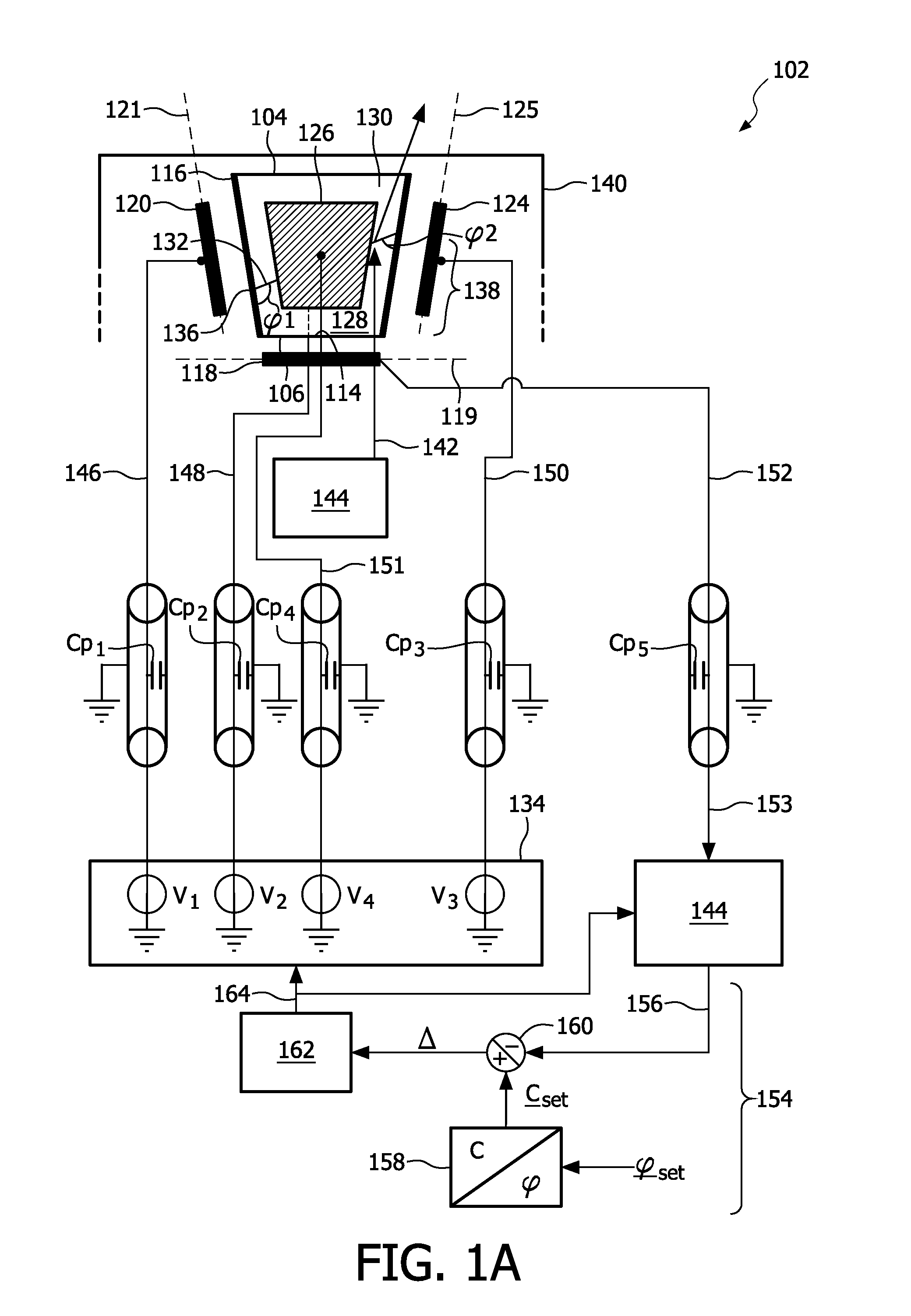
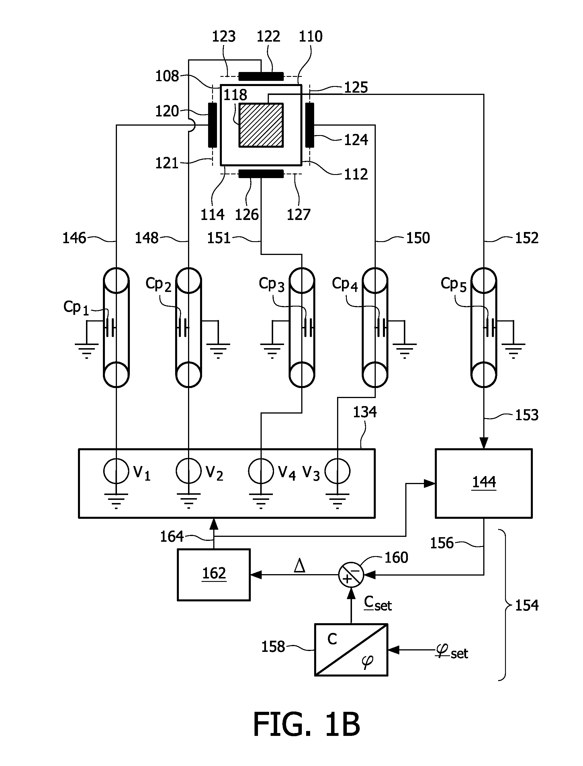
[0029]the device according to the invention is depicted in FIG. 1A, FIG. 1B and FIG. 2. FIG. 1A depicts a cross section and a bottom view of a device 102 whereas a FIG. 1B shows a bottom view of said device. The device 102 comprises a fluid chamber 104, which fluid chamber 104 has a bottom 106 and a wall having wall parts 108, 110, 112 and 114, see also FIG. 1B. The wall parts 108, 110, 112 and 114 are provided with an insulating layer 116 for preventing shortcuts, see FIG. 1A. In alternative embodiments the fluid chamber may have a conical or a cylindrical wall, or any other suitable wall. The device 102 further comprises a main electrowetting electrode 118, which is attached to the bottom 106 in this particular embodiment, and auxiliary electrowetting electrodes 120, 122, 124 and 126, see FIG. 1B, which partially surround the fluid chamber 104 and are attached to the wall parts 108, 110, 112 and 114, respectively. In this particular example, the main plane 119 and the auxiliary pl...

second embodiment

[0041]the invention is depicted in FIG. 3A, FIG. 3B and FIG. 4. FIG. 3A depicts a cross section of a device 302 whereas FIG. 3B displays a bottom view of said device 302. The device 302 comprises a fluid chamber 304, the fluid chamber 304 having a top 306 and a wall having wall parts 308, 310, 312 and 314, see FIG. 3B. The wall parts 308, 310, 312 and 314 are provided with an insulating layer 316 for preventing shortcuts, see FIG. 3A. In alternative embodiments the fluid chamber 304 may have a conical or a cylindrical wall, or any other suitable wall. The device 302 comprises a grounded main electrowetting electrode 318 attached to the top 306. In this particular example, the device 302 comprises two auxiliary electrowetting electrodes 320 and 322, which partially surround the fluid chamber 304 and which are attached to the wall parts 308 and 312, respectively.

[0042]As indicated in FIG. 3A, the fluid chamber 304 comprises a first fluid 324 and a second fluid 326, which first and sec...


PUM


Abstract

The invention relates to a device (102) arranged for measuring a geometry of a fluid meniscus (132). The device comprises a fluid chamber (104) storing a first electrically conductive fluid (128) and a second electrically insulating fluid (324). The fluids are mutually immiscible and define a fluid meniscus (132) in between them. Furthermore a main electrowetting electrode (118) and auxiliary electrowetting electrodes (120, 122, 124, 126) are provided for controlling the geometry of the fluid meniscus. Hereto a voltage source (134) for providing a voltage between the main electrowetting electrode and the auxiliary electrowetting electrodes is comprised, as well as a measurement circuit (144) for separately measuring capacitances between the main electrowetting electrode and at least two of the auxiliary electrowetting electrodes. For this purpose the measurement circuit comprises a multiplexer for demodulating a signal indicative for said capacitances. The invention further relates to a method for measuring a fluid meniscus.

Description

FIELD OF THE INVENTION[0001]The invention relates to a device for measuring a geometry of a fluid meniscus.[0002]The invention further relates to a catheter comprising such a device.[0003]The invention further relates to a method for measuring a geometry of a fluid.BACKGROUND OF THE INVENTION[0004]In WO 2006 / 035407 A1, a controllable optical lens system is disclosed. Said system comprises a lens having a chamber housing first and second fluids, wherein the interface between the fluids define a lens surface. The system further comprises an electrode arrangement comprising a first electrode and a second electrode for electrically controlling the shape of the lens surface, a feedback control loop for controlling the electrode arrangement based on a signal provided by a capacitance sensing arrangement, which capacitance sensing arrangement serves for measuring a capacitance between the first and second electrodes.[0005]The techniques disclosed in WO2006 / 035407 A1 are less suitable for g...

Claims


Application Information

Patent Timeline
IPC IPC(8): G01R27/26
CPCG01B7/28G01R27/2605G02B26/005
Inventor DE BOER, BART MICHIELDE HOOG, THOMAS JANJANSEN, THEODORUS PETRUS HENRICUS GERARDUS
Owner KONINKLIJKE PHILIPS ELECTRONICS NV
Why Eureka
Try Eureka