Thermal valve

a technology of thermocouple and valve body, which is applied in the direction of lighting and heating apparatus, process and machine control, instruments, etc., can solve the problems of wax extension technology having certain drawbacks, wax tends to lose memory, and wax tends to have a slow thermal response characteristi

Inactive Publication Date: 2014-04-29
HS MARSTON AEROSPACE
View PDF34 Cites 8 Cited by
  • Summary
  • Abstract
  • Description
  • Claims
  • Application Information

AI Technical Summary

Problems solved by technology

In practice, it has been observed that wax extension technology presents certain drawbacks.
In particular, the wax tends to lose its memory after a given number of thermal cycles.
Also, wax tends to have a slow thermal response characteristic, which makes the timing of the thermal valves difficult to manage.

Method used


Image

  • Thermal valve
  • Thermal valve
  • Thermal valve

Examples


Embodiment Construction

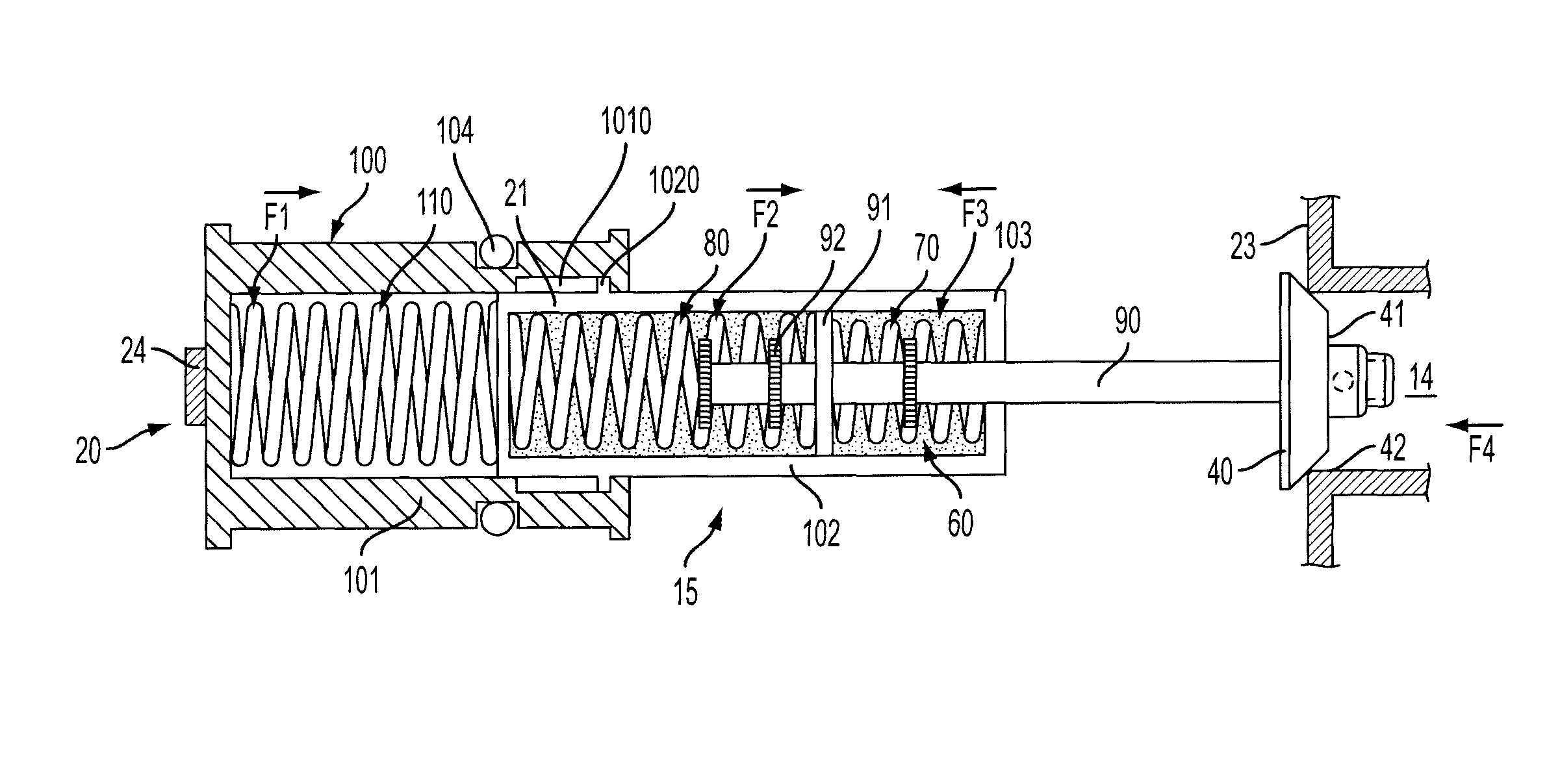
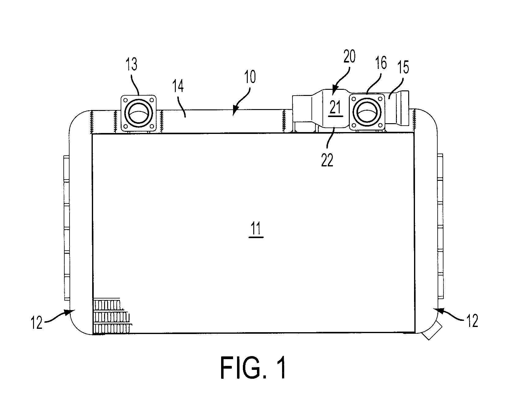
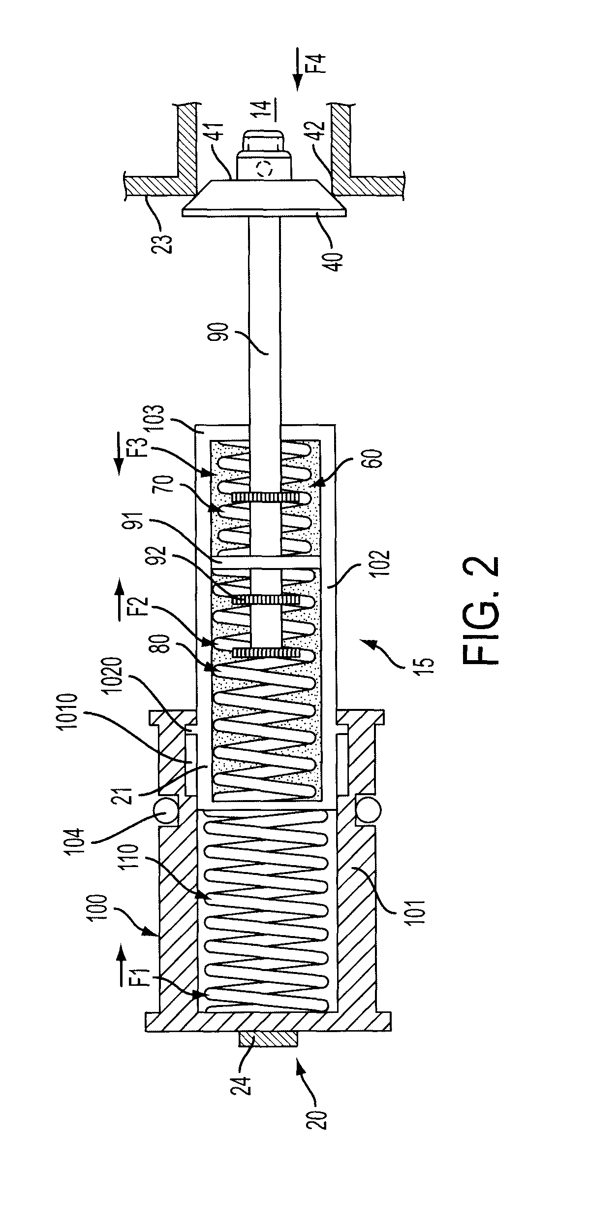
[0017]With reference to FIGS. 1-5, a heat exchange apparatus 10 is provided for use with, e.g., aircraft, automotive or gas turbine engine industries. The heat exchange apparatus 10 includes a heat exchange matrix 11 to which at least one or two matrix header tanks 12 are fluidly coupled. The heat exchange apparatus 10 receives a supply of fluid, such as oil, via inlet 13, which is fluidly coupled to conduit 14 by which the fluid flows to valve 15. Valve 15 is installed in or proximate to outlet port 16 and is configured to admit a supply of the fluid to at least the heat exchange matrix 11 in accordance with a temperature thereof so as to maintain an overall temperature of the fluid flowing through the outlet port 16. For example, where the fluid is oil, if the oil is too hot, the valve 15 may be configured to close such that the oil is forced into the heat exchange matrix 11 where it is cooled before being permitted to flow through the outlet port 16. By contrast, if the oil is co...


PUM


Abstract

A valve includes a housing and a valve seat and a structure fixedly disposed remote from the valve seat, a valve head to open and close the valve seat, fluid being permitted to flow when the valve seat is open and an elastic system anchored on the structure and coupled to the valve head, the elastic system including a biasing element and an elastic element formed of memory metal alloy disposed to contact fluid permitted to flow, the biasing element and the elastic element being configured to cooperatively move the valve head toward a valve seat open position when a fluid temperature is below a lower limit, and the biasing element and the elastic element being further configured to cooperatively move the valve head toward a valve seat closed position in opposition to the biasing element when the fluid temperature is above an upper limit.

Description

BACKGROUND OF THE INVENTION[0001]The subject matter disclosed herein relates to a thermal valve and, more particularly, to a thermal valve including an elastic element formed of memory metal alloy (elastic MMA).[0002]In various applications, such as the automotive and aircraft industries, thermal valves are commonly installed in inlet or outlet ports of heat exchangers where header tanks connect the inlet and outlet ports of a fluid stream. The valves serve to balance the flow between the inlet and the outlet ports connecting the headers and the heat exchanger core headers, thereby maintaining required fluid temperatures and pressures. To this end, the valves generally incorporate a heat and / or pressure relief mechanism whereby, if the system heat or pressure reaches a critical point, the valve allows fluid to bypass the heat exchanger core to prevent, for example, over pressurisation in the heat exchanger core and potential damage.[0003]Currently, the heat release mechanism of typi...

Claims


Application Information

Patent Timeline
Patent Type & Authority Patents(United States)
IPC IPC(8): G05D23/02
CPCF16K31/002Y10T137/7737
Inventor CAMERON, SEAN L.BURTON, CARL D.
Owner HS MARSTON AEROSPACE
Why Eureka
Try Eureka