Negative control type hydraulic system

a negative control and hydraulic system technology, applied in the field of hydraulic systems, can solve the problems of unnecessary power loss, increased manufacturing cost, complicated hydraulic system structure, etc., and achieve the effect of preventing power loss due to the use of load pressure generation units and reducing manufacturing costs

Inactive Publication Date: 2014-05-06
VOLVO CONSTR EQUIP HLDG SWEDEN AB
View PDF17 Cites 3 Cited by
  • Summary
  • Abstract
  • Description
  • Claims
  • Application Information

AI Technical Summary

Benefits of technology

[0025]An embodiment of the present invention is related to a negative control type hydraulic system, which does not require the use of a pilot pump to reduce the number of components and the manufacturing cost and thus can prevent an unnecessary power loss occurring due to the use of the pilot lamp.
[0026]An embodiment of the present invention is related to a negative control type hydraulic system, which does not require the use of a load pressure generation device between a hydraulic pump and a control valve and thus can prevent an unnecessary power loss.
[0029]In a preferred embodiment of the present invention, the negative control type hydraulic system further includes a backflow prevention check valve installed in a pilot line between the pressure reducing valve and the control lever to prevent a backflow of the hydraulic fluid when a pressure of the hydraulic fluid on the hydraulic pump side is lower than a preset pressure.
[0031]The negative control type hydraulic system as constructed above according to the embodiments of the present invention has the following advantages.
[0032]In the negative control type hydraulic system, since the hydraulic fluid from the variable-displacement hydraulic pump is used as the pilot signal pressure, the pilot pump is unnecessary, the manufacturing cost is reduced, and an unnecessary power loss due to the use of the pilot pump is prevented.
[0033]Also, since the use of the load pressure generation device between the hydraulic pump and the control valve is unnecessary, a power loss due to the use of the load pressure generation unit is prevented.

Problems solved by technology

Also, since a separate pilot pump 3 is constructed by the engine 1, the manufacturing cost is increased and the structure of the hydraulic system is complicated due to the increase of the number of components.
However, the load pressure generation device 34 is installed in the line between the hydraulic pump 30 and the control valve 32, and this causes an unnecessary power loss.

Method used


Image

  • Negative control type hydraulic system
  • Negative control type hydraulic system
  • Negative control type hydraulic system

Examples


first embodiment

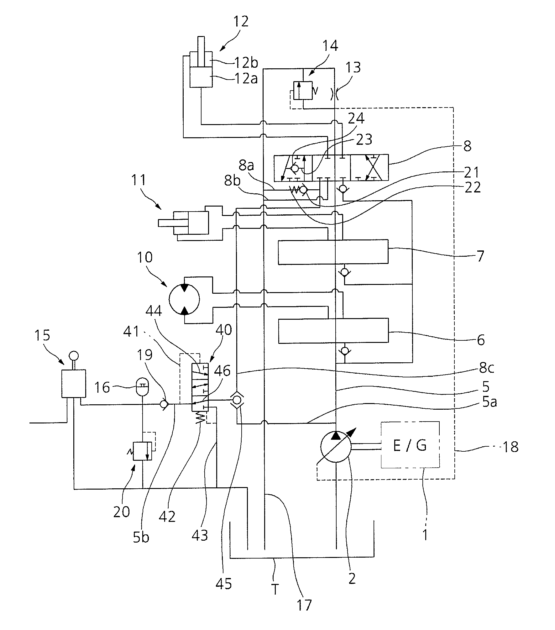
[0042]As illustrated in FIG. 3, a negative control type hydraulic system according to the present invention includes a negative control type hydraulic system, which includes an engine 1; at least one variable-displacement hydraulic pump (hereinafter referred to as a “hydraulic pump”) connected to the engine 1; at least one hydraulic actuator (e.g. a traveling motor 10, a bucket cylinder 11, and a boom cylinder 12) connected to the hydraulic pump 2; switching valves 6, 7, and 8 installed in a center bypass line 5 of the hydraulic pump 2 and shifted, in accordance with the supply of signal pressure from the outside, to control a flow of hydraulic fluid supplied to the hydraulic actuators 10, 11, and 12; pilot signal pressure generation means 13 and 14 installed on a downstream side of the center bypass line 5 to generate signal pressure for variably controlling a discharge flow rate of the hydraulic pump 2 by a negative control system; a control lever 15 outputting signal pressure in ...

second embodiment

[0058]As illustrated in FIG. 4, a negative control type hydraulic system according to the present invention includes an engine 1; at least one variable-displacement hydraulic pump (hereinafter referred to as a “hydraulic pump”) connected to the engine 1; at least one hydraulic actuator (e.g. a traveling motor 10, a bucket cylinder 11, and a boom cylinder 12) connected to the hydraulic pump 2; switching valves 6, 7, and 8 installed in a center bypass line 5 of the hydraulic pump 2 and shifted, in accordance with the supply of signal pressure from the outside, to control a flow of hydraulic fluid supplied to the hydraulic actuators 10, 11, and 12; pilot signal pressure generation means 13 and 14 installed on a downstream side of the center bypass line 5 to generate signal pressure for variably controlling a discharge flow rate of the hydraulic pump 2; a control lever 15 outputting signal pressure in proportion to a manipulation amount; a shuttle valve 45 selecting and outputting one o...


PUM


Abstract

A negative control type hydraulic system in which the use of a pilot pump and a load pressure generator between a hydraulic pump and a control valve is not required to prevent a power loss.

Description

CROSS-REFERENCE TO RELATED APPLICATION[0001]This application is based on and claims priority from Korean Patent Application No. 10-2009-132677, filed on Dec. 29, 2009 in the Korean Intellectual Property Office, the disclosure of which is incorporated herein in its entirety by reference.BACKGROUND OF THE INVENTION[0002]1. Field of the Invention[0003]The present invention relates to a hydraulic system which controls the discharge flow rate of a variable-displacement hydraulic pump by a negative control system, and more particularly to a negative control type hydraulic system, in which the use of a pilot pump is not required to prevent a power loss and also the use of a load pressure generator between a hydraulic pump and a control valve is not required.[0004]The negative control system is a control system which decreases the discharge flow rate of a hydraulic pump if pilot signal pressure generated by a pilot signal pressure generation means that is installed on the downstream side of...

Claims


Application Information

Patent Timeline
Patent Type & Authority Patents(United States)
IPC IPC(8): F16D31/02
CPCE02F9/2232E02F9/2285F15B2211/6355F15B2211/3116F15B2211/20546F15B11/055F15B2211/625F04B49/08E02F9/2296E02F9/22F04B17/05F15B13/044
Inventor CHEONG, HAE, KYUN
Owner VOLVO CONSTR EQUIP HLDG SWEDEN AB
Why Eureka
Try Eureka