
Stringer spike sheath

a stringer spike and sheath technology, applied in fishing, other angling devices, animal husbandry, etc., can solve the problems of unsatisfactory use, unfavorable use, and inability to meet the diameter of the stringer spike, etc., to achieve the effect of quick attachment and detachmen

Inactive Publication Date: 2014-05-06
DICKEY MICHAEL WILLIAM
View PDF29 Cites 3 Cited by
  • Summary
  • Abstract
  • Description
  • Claims
  • Application Information

AI Technical Summary

Benefits of technology

The present invention is a system for safely and securely attaching fishing equipment to a fishing pole. It consists of a sheath that can be easily attached to various sizes of fishing pole spikes. The sheath has an internal mechanism that includes a helical spring and three spheres that secure the fishing spike. The system allows for quick and easy attachment and detachment of fishing equipment.

Problems solved by technology

Utilizing this method is undesirable in that it requires both hands to secure the stringer onto the fisherman.
In addition, the exposed stringer spike presents a possible stabbing hazard.
In an attempt to address both issues, fishermen in the past have attached a stringer spike to their person via a wade belt pocket, but even when wading belts or similar fishing attire are worn, the pockets made to receive the stringer spike may not be uniformly snug to all spike diameters and may not tightly grip the stringer spike.
Additionally, should the fisherman be outfitted in chest high waders, the predator may drag the angler's feet from under him or her and allow the waders to fill with water—causing almost certain drowning.
Variations on the main theme have been developed, but no stringer system to date has had the capacity to reversibly couple to a stringer spike of varying diameters, allow for rapid release, and provide for the protection of the user from a stabbing hazard from an exposed, unsheathed beveled spike.
Therefore, this system can only be utilized with a specific stringer rod exhibiting a set diameter and a specifically positioned groove.
Additionally, even when the spike is sheathed, the stringer cord is still attached to the system and thus to the fisherman raising concerns of the operator's overall safety.

Method used


Image

  • Stringer spike sheath
  • Stringer spike sheath
  • Stringer spike sheath

Examples


Embodiment Construction

[0028]The following detailed description is of the best currently contemplated modes of carrying out exemplary embodiments of the present invention. The description is not to be taken in a limiting sense, but rather is made merely for the purpose of illustrating the general principles of the invention, since the scope of the invention is best defined by the appended claims and diagrams.

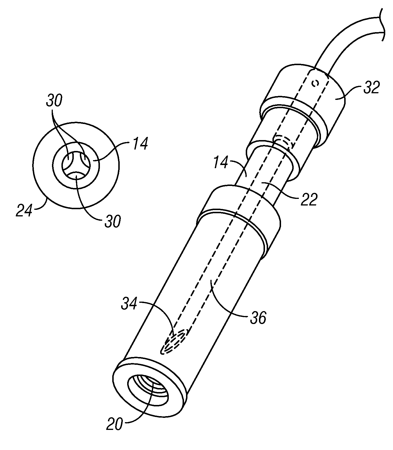
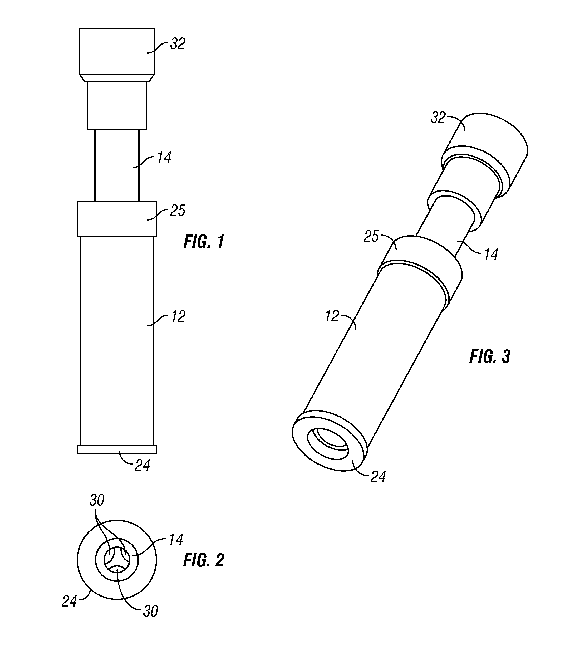
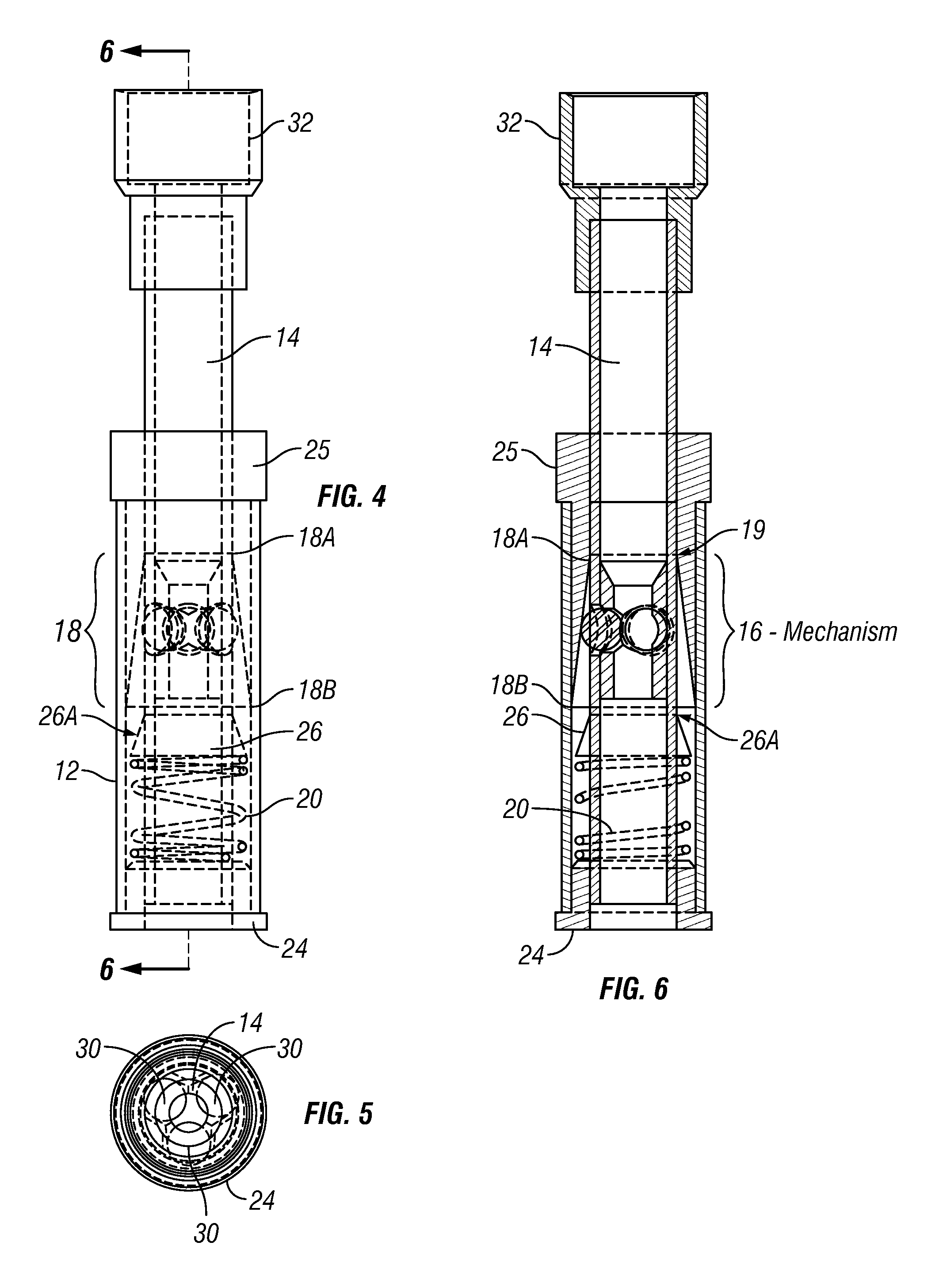
[0029]Broadly, one embodiment of the present invention provides a stringer spike sheath engineered for inshore wade fishing stringers which is designed to securely and reversibly receive a stringer spike of varying diameters for the purpose of accumulating fish on a stringer. As depicted in FIGS. 1 through 10, the device's outer shell 12 harbors a spring loaded inner stem 14 that incorporates a three-bead spike securing apparatus 16. Encircling the area of the three-beads 16 is a conically shaped bead deflector 18 that is tapered to a smaller diameter at the top 18A and widens at the base 18B. When th...


PUM


Abstract

A spring-loaded receptacle designed to accept and reversibly link a stringer spike to an angler or watercraft to collect and combine fish. The sheath is a dual lumen device comprised of an outer tubular shell, a vertically movable, hollow inner stem, and a helical spring about the lower portion of the inner stem. The inner stem manifests three holes drilled at 120 degrees from one another and beads placed in these holes for engaging and securing the spike. A conically shaped bead deflector skirts the inner stem, surrounds the bead system, and exhibits a widening circumference as it descends into the outer shell. Spike insertion is accomplished by depressing the stem, compressing the spring, and allowing bead movement downward and outward away from the sheath center. The beads grip the spike when the stem is released, the spring expands, and the beads move into the bead deflector's tapered angle.

Description

BACKGROUND OF THE INVENTION[0001]1. Field of the Invention[0002]The present invention relates to a fish stringing system, and more particularly, to an improved fish stringing system manifesting a point of connection between stringer and fisherman that allows for safe, reversible coupling, ease of fish attachment and detachment, and quick release.[0003]2. Description of the Related Art[0004]When in shore wade fishing for sport or leisure, it has long been customary to attach caught fish to ones self via a small line generally referred to as a stringer. This stringer may consist of a rope or cord exhibiting a plurality of hook closures for fish attachment or, as with this invention, a single piece of rope designed for successive fish attachment. In the later, once the fisherman has made his catch, the string is traditionally guided through the fish's gills and brought out of the mouth through the use of an attached beveled tip spike. Fish are collected in series and comprise what is c...

Claims


Application Information

Patent Timeline
Patent Type & Authority Patents(United States)
IPC IPC(8): A01K65/00
CPCA01K65/00
Inventor DICKEY, MICHAEL, WILLIAM
Owner DICKEY MICHAEL WILLIAM
Learn More