Check patentability & draft patents in minutes with Patsnap Eureka AI!

Projection display device

a projection display and display screen technology, applied in the field of projection display devices, can solve the problems of increased illuminance unevenness and color increased illuminance unevenness and color unevenness and difficult entry of high-order diffracted light, etc., to achieve simple structure and correct the effect of illumination distribution on the image display surface of the screen

Inactive Publication Date: 2014-05-06
MITSUBISHI ELECTRIC CORP
View PDF21 Cites 1 Cited by
  • Summary
  • Abstract
  • Description
  • Claims
  • Application Information

AI Technical Summary

Benefits of technology

The present invention allows for the correction of the brightness of the display screen with a simple structure.

Problems solved by technology

Reducing the parts count of optical systems and limiting the use of aspheric lenses in order to reduce the size and cost of the optics generally leads to greater aberrations in the optical systems and more uneven illuminance and color on the image display surface of the screen.
The more finely spaced the pixels are, accordingly, the more difficult it becomes for high-order diffracted light to enter the projection optics, and the less diffracted light can be used for image projection.
In addition, if there are large differences in the amount of incident light or its angle of incidence within the image formation region of the light valve (the illuminated area), differences in the amount of diffracted light in the entrance plane of the projection optics become large, resulting in increased illuminance unevenness and color unevenness on the image display surface of the screen.
Reducing the aperture diameter of the optical system reduces the amount of diffracted light that enters the optical system, however, which tends to increase the effect, on the image display surface of the screen, of uneven illuminance and color due to the effect of optical aberration and the effect of the finer spacing in the light valve.

Method used


Image

  • Projection display device
  • Projection display device
  • Projection display device

Examples


first embodiment

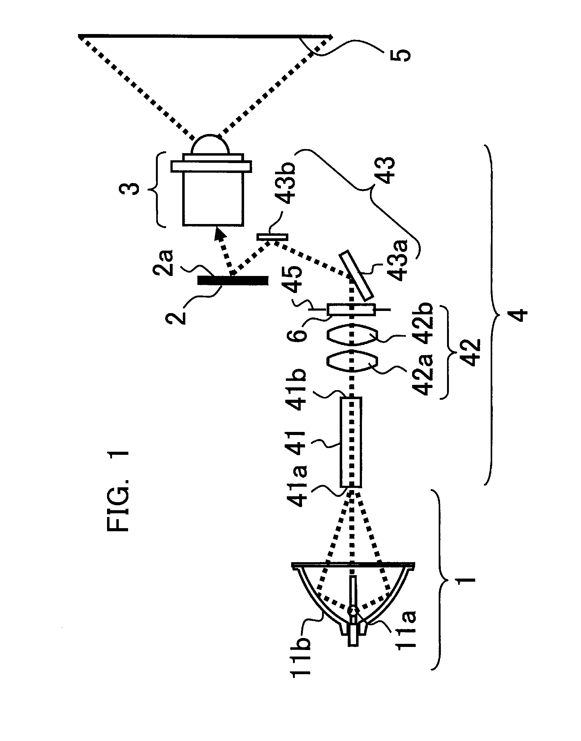
[0027]FIG. 1 schematically illustrates the structure of the optical system of a projection display device according to the first to third embodiments of the invention. As shown in FIG. 1, the projection display device in the first embodiment has a source lamp 1 used as a light source for emitting a light beam (indicated by dotted lines in the drawing), a DMD element 2 used as a light valve having an image formation region (illuminated surface) 2a for forming an image according to input image information, an illumination optical system 4 for guiding the light beam emitted from the source lamp 1 onto the image formation region 2a of the DMD element 2, and a projection optical system 3 for expanding the light beam modulated by the image formed in the image formation region 2a of the DMD element 2 and projecting it onto a screen 5.

[0028]The source lamp 1 includes, for example, a light emitting element11a for emitting white light and an elliptical mirror 11b disposed around the light emi...

second embodiment

[0064]An aperture regulation member 62 that further improves the illuminance distribution (FIG. 12) obtained by use of the aperture regulation member 61 (FIG. 11) in the first embodiment will be described in the second embodiment. Segment 107 shown in FIG. 8 has less light than the other segments. An aperture section 62a for improving segment 107 will now be considered.

[0065]FIG. 13 is a frontal view showing the shape of the aperture section 62a of the aperture regulation member 62. In FIG. 13, in addition to aperture region 61b in aperture regulation member 61, the aperture section 62a of aperture regulation member 62 has a rectangular aperture region 62c. This aperture region 62c corresponds to segment 107 on the image display surface of the screen 5.

[0066]FIG. 14 shows the illuminance distribution on the image display surface of the screen 5 when aperture regulation member 62 is employed. The vertical axis indicates relative brightness and the horizontal axis indicates segments o...

third embodiment

[0068]An aperture regulation member 63 that further improves the illuminance distribution (FIG. 14) obtained by use of the aperture regulation member 62 (FIG. 13) in the second embodiment will be described in the third embodiment. As shown in FIG. 14, in the second embodiment the relative brightness of segment 108 is brighter than the relative brightness of the other segments. The aperture regulation member 63 in the third embodiment has a shape that can reduce the relative brightness of segment 108. FIG. 15 is a frontal view schematically showing the shape of the aperture section 63a of the aperture regulation member 63 in the third embodiment. The aperture section 63a of the aperture regulation member 63 shown in FIG. 15 is shaped with a protrusion that blocks light in an area 63d of the aperture regulation member 63 corresponding to segment 108 of the image display surface of the screen 5.

[0069]FIG. 16 shows the illuminance distribution on the image display surface of the screen ...


PUM


Abstract

A projection display device has an illumination optical system that includes a light-intensity equalization element, a first optical system, and an aperture regulation member. The aperture regulation member is disposed at a position that is not optically conjugate with the screen, and the aperture regulation member has at least one of the following, using measured or calculated relative illuminances at each of multiple segments of the image formation region or screen: an aperture expansion part provided at a position corresponding to a segment with a low relative illuminance, the aperture expansion part being a cutout that narrows the light-blocking section and widens the aperture section; an aperture contraction part provided at a position corresponding to a segment with a high relative illuminance, the aperture contraction part being a protrusion that widens the light-blocking section and narrows the aperture section.

Description

TECHNICAL FIELD[0001]The present invention relates to a projection display device that displays an image by projecting a beam of light modulated by a light valve onto a screen.BACKGROUND ART[0002]Reducing the parts count of optical systems and limiting the use of aspheric lenses in order to reduce the size and cost of the optics generally leads to greater aberrations in the optical systems and more uneven illuminance and color on the image display surface of the screen. Here, uneven illuminance means a distribution, mapped with respect to position expressed in two dimensions in an arbitrary plane, that shows highs and lows of illuminance (a non-uniform illuminance distribution), and uneven color means a distribution, mapped with respect to position expressed in two dimensions in an arbitrary plane, that shows color variations (a non-uniform chromaticity distribution).[0003]Along with the recent increasing resolution and decreasing size of light valves has come a reduction in the spa...

Claims


Application Information

Patent Timeline
Patent Type & Authority Patents(United States)
IPC IPC(8): G03B21/14
CPCH04N9/3152G02B27/0994G03B21/208G03B21/2053G02B5/00G02B26/10G02F1/1335G03B21/14
Inventor KOJIMA, KUNIKOTAKEUCHI, HAYATOYAMADA, AKIHIRO
Owner MITSUBISHI ELECTRIC CORP
Features
  • R&D
  • Intellectual Property
  • Life Sciences
  • Materials
  • Tech Scout
  • Unparalleled Data Quality
  • Higher Quality Content
  • 60% Fewer Hallucinations
Learn More