Stacked solar cell device

a solar cell and battery technology, applied in the direction of semiconductor devices, photovoltaics, electrical devices, etc., can solve the problems of increased manufacturing costs, increased work costs, and inability to effectively convert photoelectrically with respect to reflected and scattered lights coming from plural directions around

Inactive Publication Date: 2014-05-06
SPHELAR POWER
View PDF32 Cites 0 Cited by
  • Summary
  • Abstract
  • Description
  • Claims
  • Application Information

AI Technical Summary

Benefits of technology

[0029]The rod-shaped solar battery cell includes the rod-shaped substrate, the another (separate) conductive layer of a conductivity type different from the substrate, the partial cylindrical pn junction, and the first and second strap-shaped electrodes which are provided to both ends of the cell with respect to the axial center of the substrate being sandwiched therebetween and are connected to the pn junction. Thus, a distance from each point on the pn junction to the first and second electrodes is maintained at an almost constant small value. Therefore, the entire pn junction generates uniformly photovoltaic power, enabling keeping the photoelectric conversion efficiency of the rod-shaped solar battery cell high.
[0030]In a case of configuring the rod light receiving solar battery sub module by arranging a plurality of rod-shaped solar battery cells in parallel to be connected in series via the first and second electrodes, the voltage generated in the sub module can be varied by changing the diameter of the substrate to change the number of the plurality of rod-shaped solar battery cells.
[0030]In a case of configuring the rod light receiving solar battery sub module by arranging a plurality of rod-shaped solar battery cells in parallel to be connected in series via the first and second electrodes, the voltage generated in the sub module can be varied by changing the diameter of the substrate to change the number of the plurality of rod-shaped solar battery cells.
[0032]In the rod-shaped solar battery cell, since the length thereof in a direction of the axial center can be set several to a dozen times the diameter of the substrate, the light receiving area can be significantly increased compared with the granular solar battery cell. Additionally, a plurality of rod-shaped solar battery cells can be arranged densely in parallel to constitute the rod light receiving solar battery sub module, and a ratio of the light receiving area to a projected area of the sunlight can be set larger to increase light receiving efficiency for receiving the sunlight.

Problems solved by technology

However, the tandem solar battery and the stacked solar battery have a flat receiving surface, and receive the light from the receiving surface only; thus, they cannot convert effectively photoelectrically with respect to reflected and scattered lights coming from plural directions around.
Accordingly, there is a problem in which the pn junction which intrinsically can output the high output current singularly cannot exhibit the output to a maximum extent.
In order to grow continuously the different kinds of semiconductors, the lattice constants have to be matched, the selectable semiconductor is limited, and it is necessary to control the precise composition in the thin film crystal growth, leading to an increased cost for a manufacturing device and works.

Method used


Image

  • Stacked solar cell device
  • Stacked solar cell device
  • Stacked solar cell device

Examples


embodiment

[0109]Hereinafter, an embodiment of the present invention will be described with reference to the drawings.

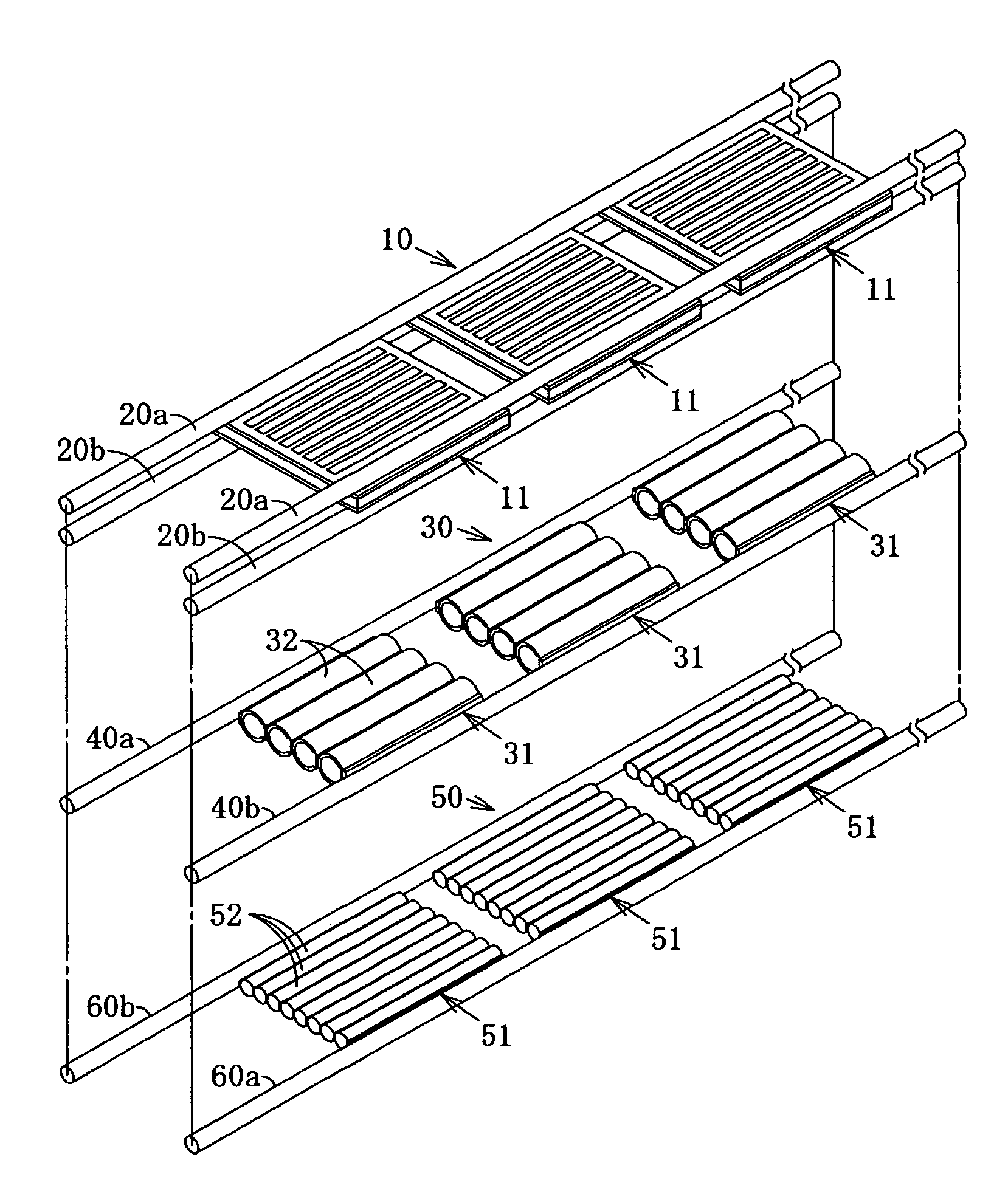
[0110]As shown in FIGS. 11 to 15, a light collecting type stacked solar battery device 1 comprises an enclosure case 2 made of a metal plate, stacked solar battery units 4 respectively housed in three recesses 3 of the enclosure case 2, a sealing material 63 (not shown in FIG. 13) filled in each of the recesses 3, a cover glass 5 arranged on an incident side of sunlight, end stopping blocks 6 arranged at both ends of each of the recesses 3 of the enclosure case 2.

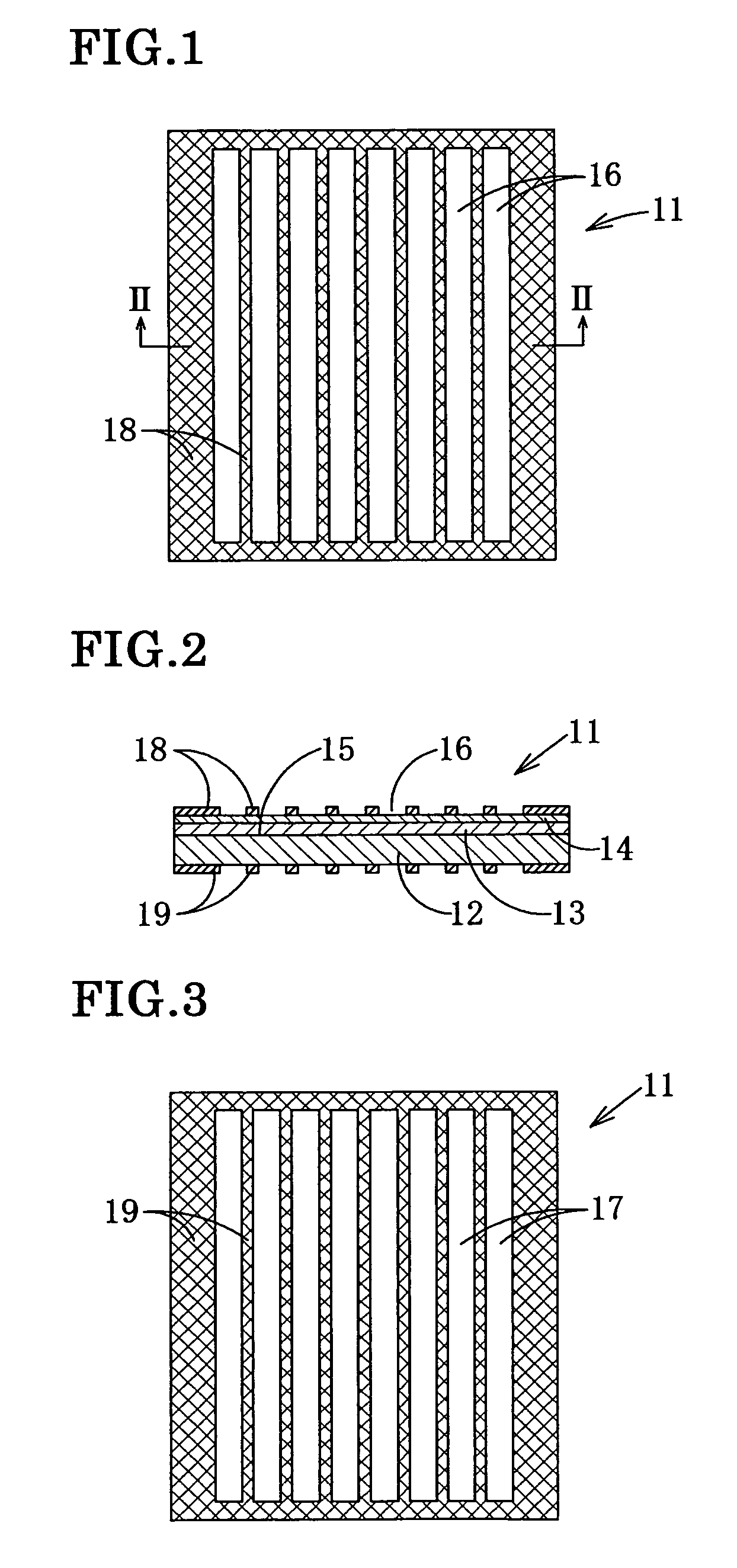
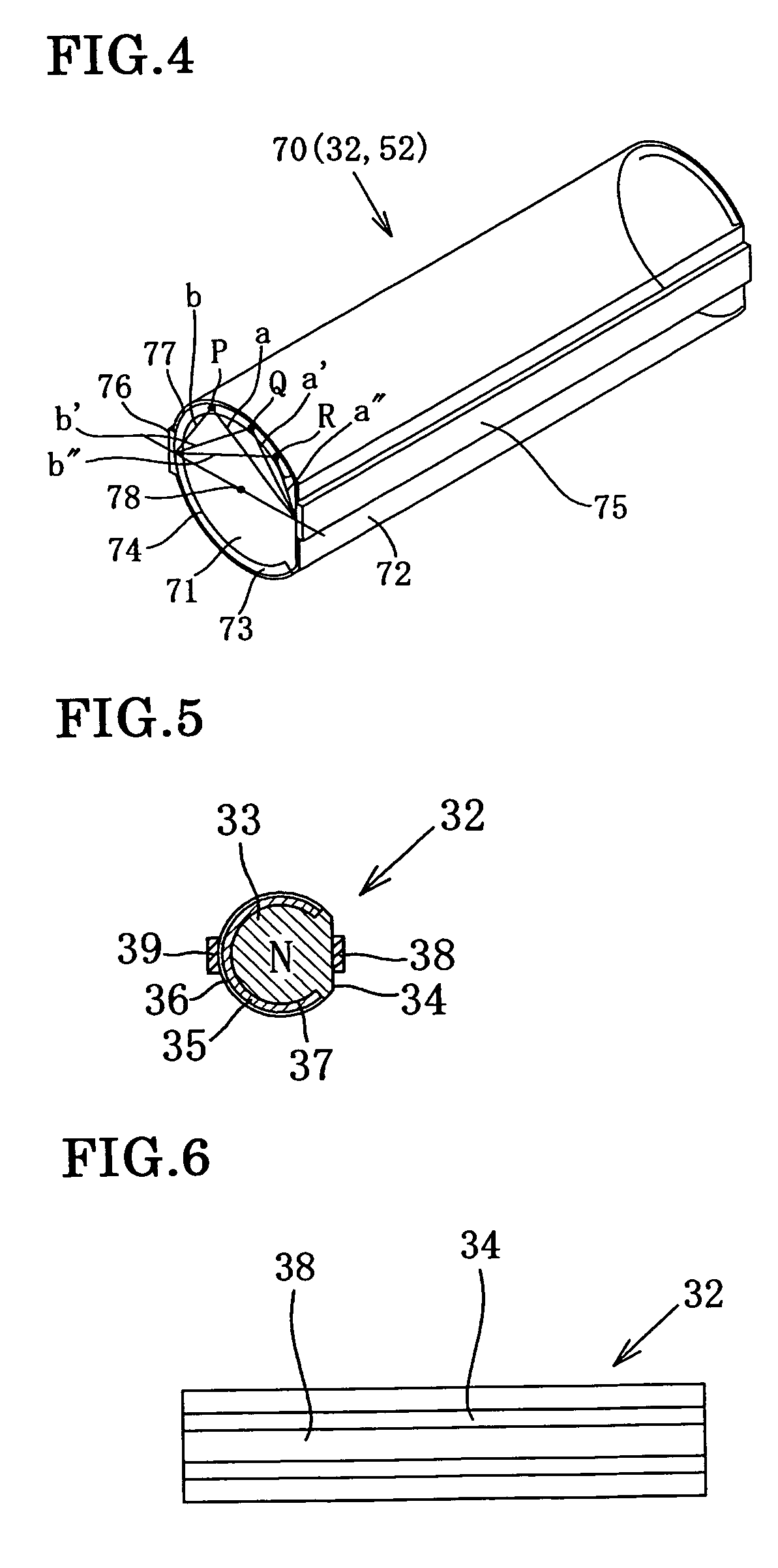
[0111]The stacked solar battery unit 4 comprises three kinds of solar battery modules 10, 30 and 50 which are different from one another in the sensitivity wavelength band, and the shorter center wavelength of the sensitivity wavelength band the solar battery module has, the closer to the incident side of the sunlight of the solar battery module is positioned. The first solar battery module 10 has five planar light rec...


PUM


Abstract

This stacked solar battery device includes a plurality of solar battery units 4, an enclosure case made of a metal plate to house these solar battery units 4 therein, a cover glass having a partial cylindrical lens formed. The plurality of solar battery units 4 are housed in a plurality of recesses of the enclosure case, and are sealed with a sealing material of synthetic resin. The solar battery unit 4 has a planar light receiving solar battery module 10, and rod light receiving solar battery modules 30 and 50 stacked so that the module having a shorter center wavelength of the sensitivity wavelength band is positioned closer to the incident side of the sunlight. The solar battery module 10 is configured so that five planar light receiving solar-battery cells 11 are connected in parallel with four connection rods 20a and 20b, and the sunlight modules 30 and 50 are configured so that five sub modules 31 and 51 are connected in parallel respectively with the connection rods 40a, 40b, 60a and 60b. The sub modules 31 and 51 are configured so that a plurality of rod-shaped solar battery cells 32 and 52 respectively are connected in series.

Description

TECHNICAL FIELD[0001]The present invention relates to a stacked solar battery device in which a plurality of solar battery modules having different sensitivity wavelength bands are stacked in order to effectively utilize wavelength components in a wide range of sunlight spectrum. Particularly, the invention relates to the stacked solar battery device in which the solar battery module is stacked so that the larger the forbidden band of a semiconductor the solar battery module has, that is, the shorter center wavelength of the sensitivity wavelength band the solar battery module has, the closer to an incident side of sunlight the solar battery module is positioned.BACKGROUND TECHNOLOGY[0002]For the spread of the solar battery device, there are important elements such as convenience, photoelectric conversion efficiency, production cost, quality stability, lifetime of the device, energy consumption required for manufacturing the solar battery, disposal after use and the like of the sola...

Claims


Application Information

Patent Timeline
Patent Type & Authority Patents(United States)
IPC IPC(8): H01L31/042
CPCH01L31/02008H01L31/035281H01L31/0504H01L31/0543H02S40/22Y02E10/52H01L31/042
Inventor NAKATA
Owner SPHELAR POWER
Why Eureka
Try Eureka