Method and system for fluid wave energy conversion

a technology of fluid wave energy and conversion method, which is applied in the direction of generator/motor, machine/engine, generator control, etc., can solve the problems of increasing the difficulty of energy harvesting

Inactive Publication Date: 2014-05-06
QORTEK
View PDF9 Cites 2 Cited by
  • Summary
  • Abstract
  • Description
  • Claims
  • Application Information

AI Technical Summary

Benefits of technology

[0012]It is a further object of the invention to provide a method and apparatus to substantially increase the volumetric proportion of electromechanical coupled materials that are being excited at any given moment, at or near resonance, by the converted mechanical energy.
[0015]Certain of these and other objects are accomplished in part by a system for converting kinetic wave energy from a dynamic fluid into electrical power including a structural housing containing a piezokinetic assembly having a plurality of piezokinetic elements, panels or members, and a dynamic assembly, coupled to the piezokinetic assembly; and an electronics module coupled to the piezokinetic assembly. When the system operates in a dynamic fluid medium, the dynamic fluid medium's energy (wave or current flow) mechanically couples with the structural housing causing a resulting displacement of the dynamic assembly contained therein. The displacement of the dynamic assembly causes the plurality of electromechanical coupled elements to simultaneously flex, causing an electrical charge to be generated at each individual element because of the direct piezoelectric effect.

Problems solved by technology

This type of energy harvesting, becomes even more important and difficult when the environment is one that involves extremes such as weather and location.
Methods and apparatus for converting environmental energy from dynamic fluids present unique problems while simultaneously offering an almost unlimited potential if one can overcome the challenges that arise from the dynamic fluid environment.
Energy harvesting from and application to airborne, fixed or waterborne systems offer unique challenges of materials and design since they must often function in some of the most extreme environments that the planet has to offer.
One such extreme environment that offers unique problems is energy conversion for marine or submerged electrical systems that are traditionally battery powered.
Generally a drawback of battery power is that the useful life of the battery is limited unless solar energy is used to recharge the batteries.
However, when the system is submerged, employed in an environment with limited solar exposure or a dynamic environment, the various approaches are limited.
A problem with this approach is that it completely relies upon the thermal gradient that exists in the sea water over intervening depth of the thermal pipe.
This renders thermal approaches very difficult to implement for floating or submerged applications without lengthy cables, which may not be feasible in many, especially shallow water applications.
The problem is that marine environment based excitations are very low, typically only a few Hz to less than a Hz, while resonance of electrostrictive or piezoelectric beams and plates or beams and plates that incorporate piezoelectric or electrostrictive materials or composites are typically at acoustic frequencies of tens to hundreds of Hz.
This dampening effect limits the system's energy output as the design allows only one piezoceramic beam to generate charge at a time.
Also a system employing a ball striker method would have significant limitations in a liquid environment.

Method used


Image

  • Method and system for fluid wave energy conversion
  • Method and system for fluid wave energy conversion
  • Method and system for fluid wave energy conversion

Examples


Embodiment Construction

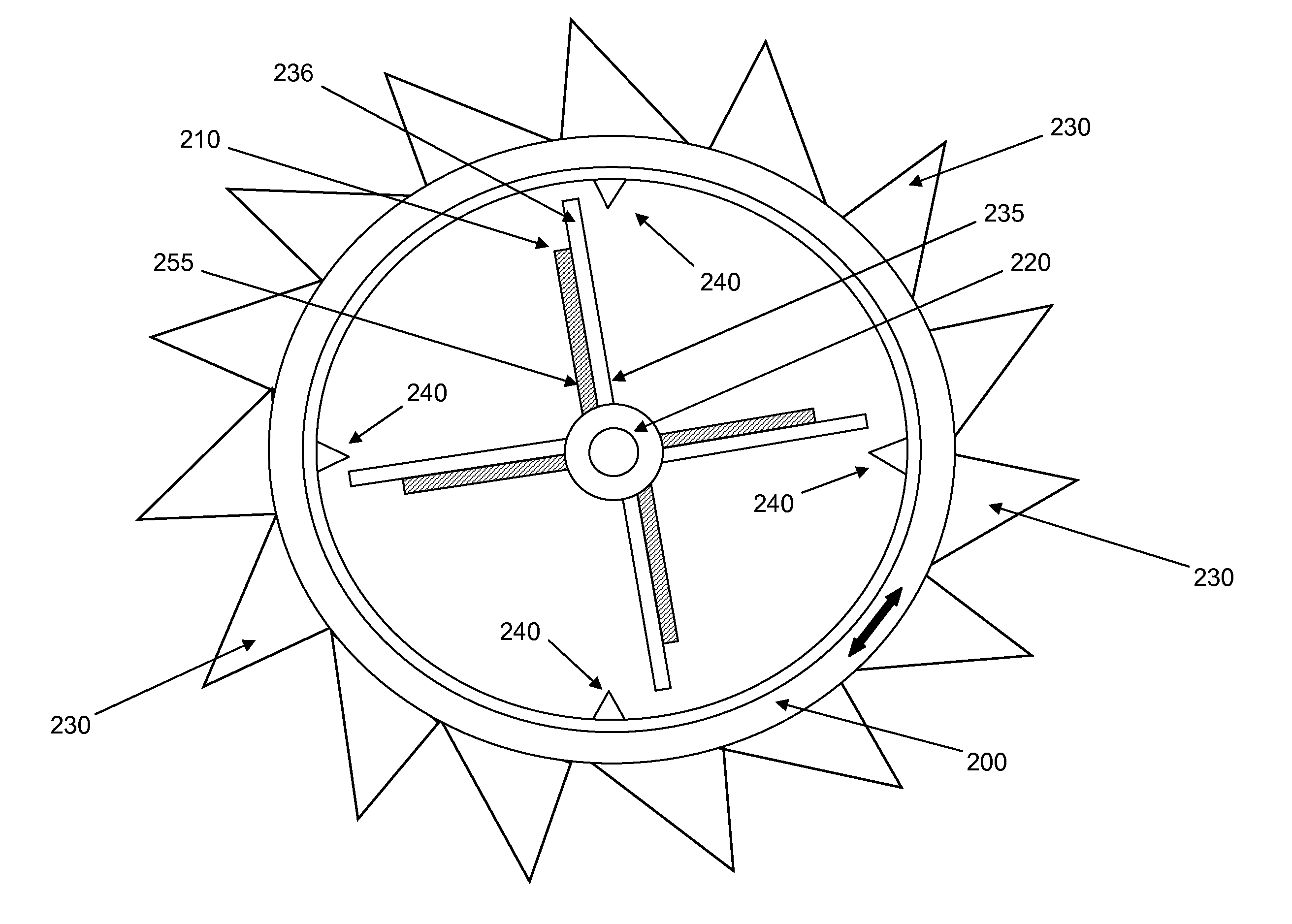
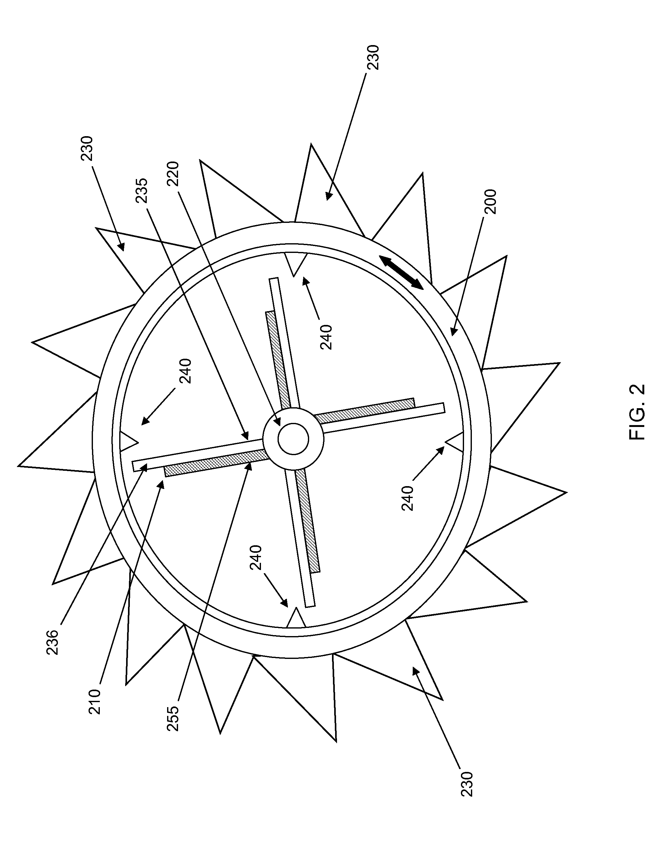
[0035]Referring now to the figures wherein like reference numbers denote like elements, FIG. 2 and FIG. 5 both illustrate embodiments of the wave energy conversion apparatus employing a plurality of piezokinetic elements. The apparatus features a rotating ring or collar 200 having a plurality of turbine or similar blades 230 attached to its outer surface. The blades 230 are disposed at an angle and are configured to couple with, interact with or otherwise be responsive to movement of an external dynamic medium such as a dynamic fluid around the outer surface of the rotating collar 200. The blades 230 of the rotating collar 200 may incorporate a variable pitch angle. A piezokinetic assembly 220 features a plurality of piezokinetic elements 210, attached thereto projecting outward from a center axis. Typically the piezokinetic elements 210 are disposed to form a cantilevered structure or variations thereof, however other configurations of the piezokinetic elements are contemplated and...


PUM

PropertyMeasurementUnit
fluid wave energyaaaaaaaaaa
electrical energyaaaaaaaaaa
electrical chargeaaaaaaaaaa

Abstract

A system for converting kinetic wave energy from a dynamic fluid into electrical power, the system including a structural housing containing a piezokinetic assembly having a plurality of electromechanical coupled elements, and a dynamic assembly, coupled to the piezokinetic assembly; and charge storage devices or power consumption devices in an electronics module coupled to the piezokinetic assembly. When the exposed to the dynamic fluid medium, the dynamic fluid medium's wave energy couples with the structural housing causing a resulting displacement of the dynamic assembly contained therein. The displacement of the dynamic assembly causes a plurality of the electromechanical coupled elements to simultaneously flex, generating an electrical charge which may be either stored in the charge storage device or which may directly power the power consumption device.

Description

I. FIELD OF THE INVENTION[0001]This invention relates in general to the field of energy conversion systems and in particular to the field of conversion of fluid wave energy into electrical energy.II. DESCRIPTION OF THE PRIOR ART[0002]In today's economic and environmental climate it has become increasingly desirable to perfect ways to harvest and convert environmental energy into electrical power that can be used to power electrical devices. This type of energy harvesting, becomes even more important and difficult when the environment is one that involves extremes such as weather and location.[0003]Methods and apparatus for converting environmental energy from dynamic fluids present unique problems while simultaneously offering an almost unlimited potential if one can overcome the challenges that arise from the dynamic fluid environment. Energy harvesting from and application to airborne, fixed or waterborne systems offer unique challenges of materials and design since they must ofte...

Claims


Application Information

Patent Timeline
Patent Type & Authority Patents(United States)
IPC IPC(8): F03B13/10
CPCY02E10/38F03B13/14F05B2270/709Y10T29/42Y02E10/30Y02E10/20
Inventor KNOWLES, GARETH J.BIRD, ROSS
Owner QORTEK
Why Eureka
Try Eureka