Airflow control system with external air control

Active Publication Date: 2014-05-13
AMAZON TECH INC
View PDF20 Cites 32 Cited by
  • Summary
  • Abstract
  • Description
  • Claims
  • Application Information

AI Technical Summary

Benefits of technology

[0007]Various embodiments of a system and method for cooling electronic equipment are disclosed. According to one embodiment, a cooling system includes one or more air channeling sub-systems that provide cooling air to electronic equipment, at least one heat removal sub-system that removes heat from the cooling air in at least one of the air channeling sub-systems, at least one temperature sensor that measur

Problems solved by technology

Some known electronic components generate waste heat energy when energized.
Moreover, some known data centers include a plurality of racking systems that have a plurality of configurations that are non-uniform with respect to component density and usage such that each racking system ge

Method used


Image

  • Airflow control system with external air control
  • Airflow control system with external air control
  • Airflow control system with external air control

Examples


Embodiment Construction

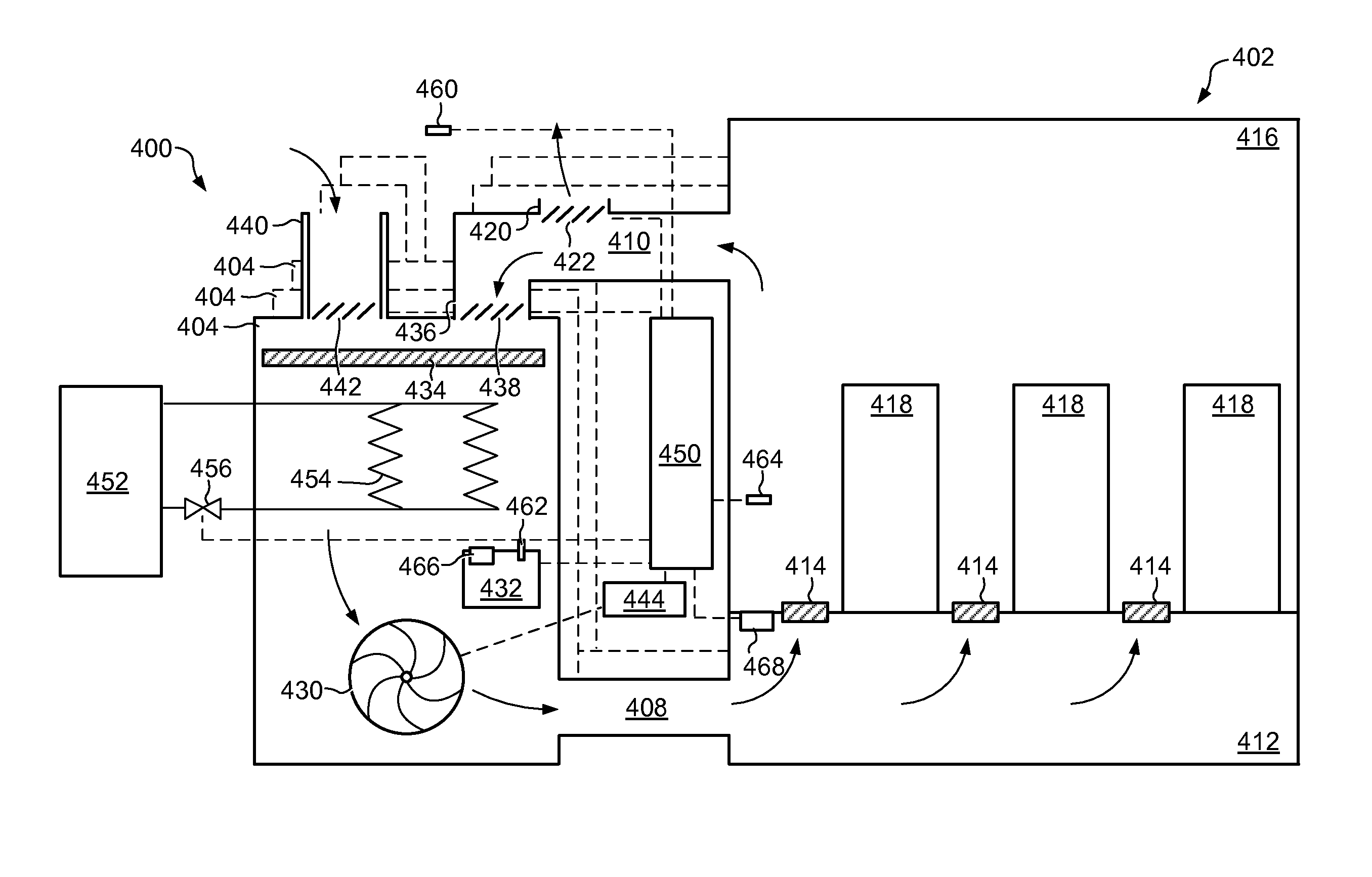
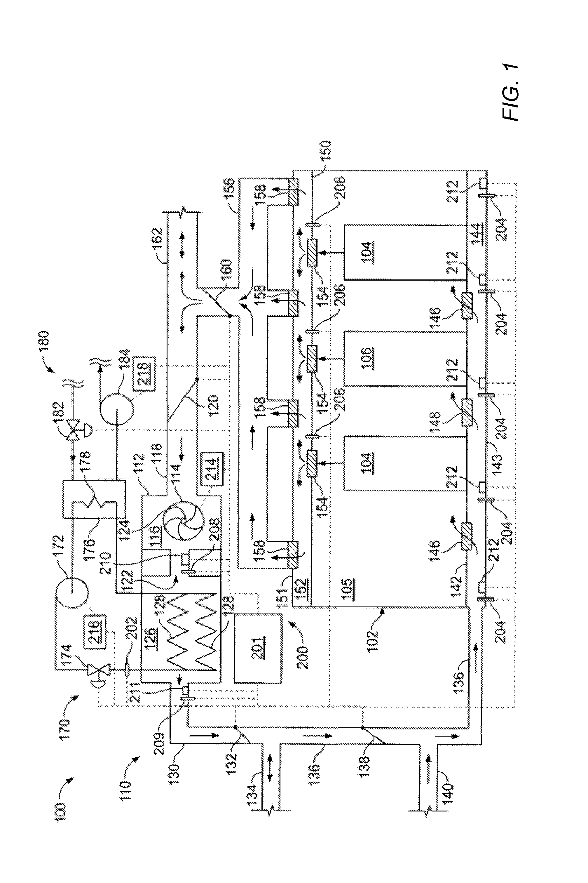
[0029]FIG. 1 is a schematic view of an exemplary data center cooling system 100. System 100 is configured to remove waste heat generation from a data center 102. Data center 102 includes at least one high-density equipment rack system, or high-density rack 104, and at least one low-density equipment rack system, or low-density rack 106. Racks 104 and 106 are substantially similar with the exception of a configuration of electronic components (not shown) within each of racks 104 and 106 and the associated waste heat generation. Typically, waste heat generation from high-density rack 104 is greater than waste heat generation from low-density rack 106 due to the greater concentration of waste heat sources within rack 104 as compared to rack 106. Racks 104 and 106 are positioned within a room 105 of data center 102.

[0030]System 100 includes a fluid transport sub-system that, in the exemplary embodiment, is an air handling sub-system 110. Sub-system 110 is coupled in flow communication w...


PUM


Abstract

A cooling system includes one or more air channeling sub-systems that provide cooling air to electronic equipment, at least one heat removal sub-system that removes heat from the cooling air in at least one of the air channeling sub-systems, at least one temperature sensor measures a wet bulb temperature of outside air, and at least one controller. At least one of the air channeling sub-systems includes an outside air damper operable allow outside air into the air channeling sub-system. The at least one controller at least partially opens the outside air damper if a wet bulb temperature measured at the at least one temperature sensor drops to or below a predetermined temperature.

Description

[0001]This application claims benefit of U.S. Provisional Patent Application 60 / 953,078 filed Jul. 31, 2007 which is hereby incorporated by reference in its entirety.BACKGROUND[0002]1. Field of the Invention[0003]The present invention relates generally to cooling systems and more particularly, to methods and apparatus for cooling electronic components.[0004]2. Description of the Related Art[0005]Some known electronic components generate waste heat energy when energized. This heat energy should be removed to mitigate a potential for component overheating and subsequent malfunction. Computer systems typically include a number of such components, or waste heat sources, that include, but are not limited to, printed circuit boards, mass storage devices, power supplies, and processors. For example, one personal computer system may generate 100 watts to 150 watts of waste heat and some larger computers with multiple processors may generate 250 watts of waste heat. Some known computer syste...

Claims


Application Information

Patent Timeline
IPC IPC(8): H05K5/00F24F11/00F24F7/08F24F7/10
CPCH05K7/20745F24F11/00H05K7/20836F24F7/08F24F7/10Y02B30/542H05K7/20209H05K5/00
Inventor MORALES, OSVALDO, P.
Owner AMAZON TECH INC
Why Eureka
Try Eureka