Autonomous controlled headroom low dropout regulator for single inductor multiple output power supply

a technology of single inductor and multiple output power supply, which is applied in the direction of power conversion systems, instruments, dc-dc conversion, etc., can solve the problems of power supply also generating substantial noise and ripple in the output voltage, and most electronic circuits cannot operate correctly over this wide voltage rang

Active Publication Date: 2014-05-13
INTEGRATED DEVICE TECH INC
View PDF22 Cites 20 Cited by
  • Summary
  • Abstract
  • Description
  • Claims
  • Application Information

AI Technical Summary

Problems solved by technology

Most electronic circuits cannot operate correctly over this wide of a voltage range.
Linear audio circuits, RF circuits and timing clocks are examples of circuits that could produce errors if powered by either widely varying or noisy voltage sources.
However, while switch-mode power supplies generally exhibit high efficiency, these power supplies also generate substantial noise and ripple in the output voltage.
Conventional SIMO supplies undesirably require a complex central controller that must not only regulate a bias voltage necessary to generate each of the output voltages, but must also provide different sets of timing signals to control the switching required to generate each individual output voltage.
However, while linear regulators typically provide output voltages that exhibit less noise than switch-mode power supplies, linear regulators are typically much less efficient than switch-mode power supplies.
However, both of these schemes are very inefficient, unless the output voltage of the LDO regulator happens to be very close to the input voltage of the LDO.

Method used


Image

  • Autonomous controlled headroom low dropout regulator for single inductor multiple output power supply
  • Autonomous controlled headroom low dropout regulator for single inductor multiple output power supply
  • Autonomous controlled headroom low dropout regulator for single inductor multiple output power supply

Examples


Embodiment Construction

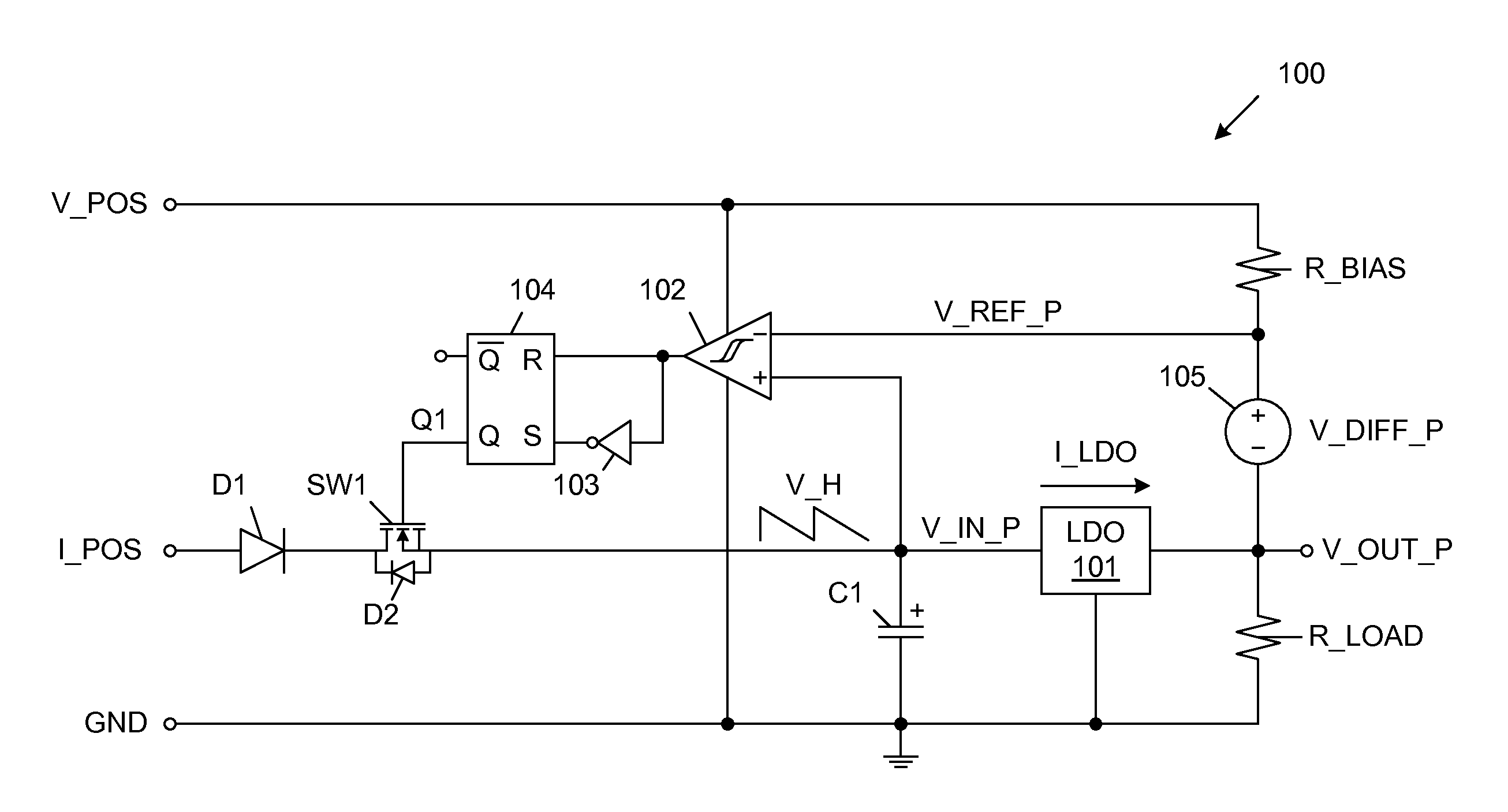
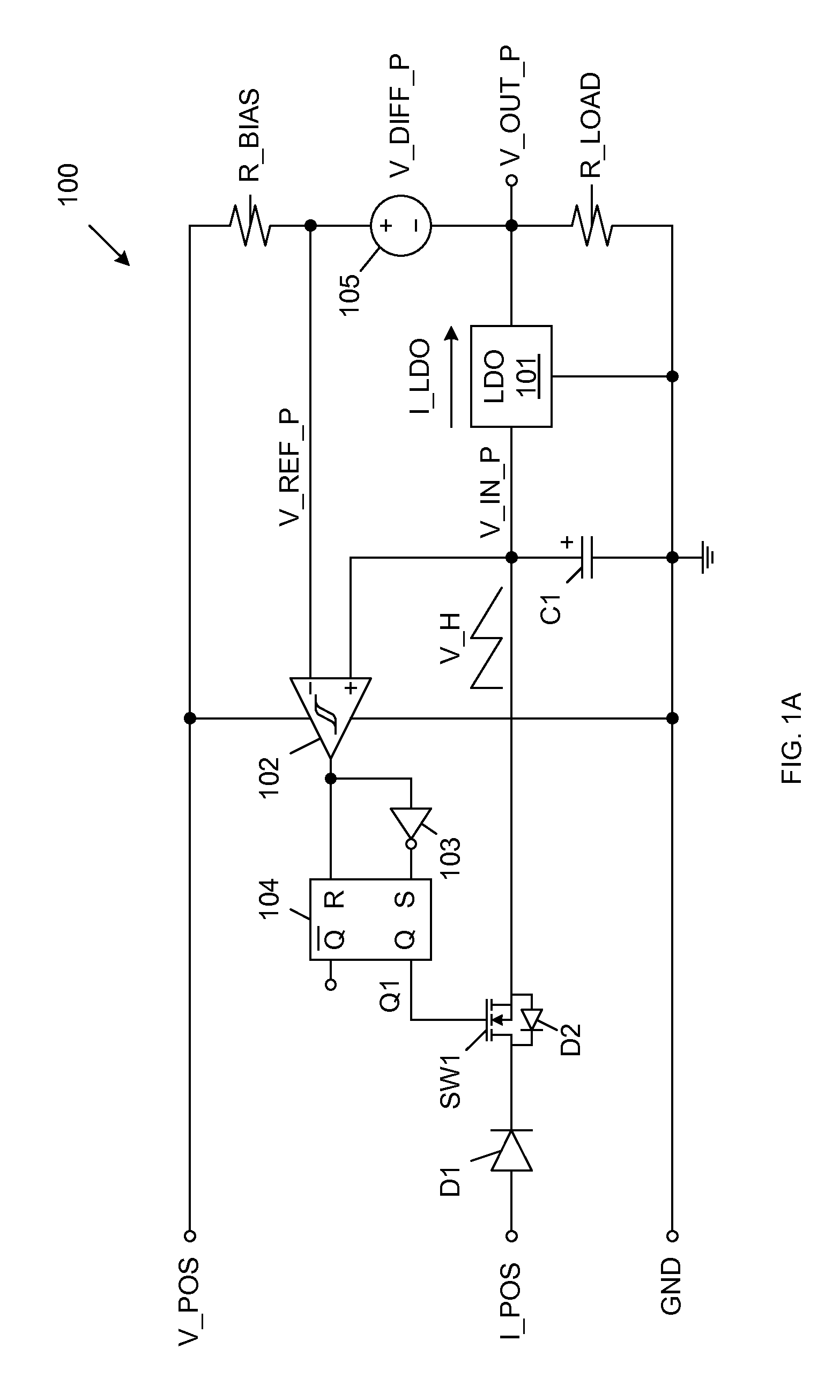
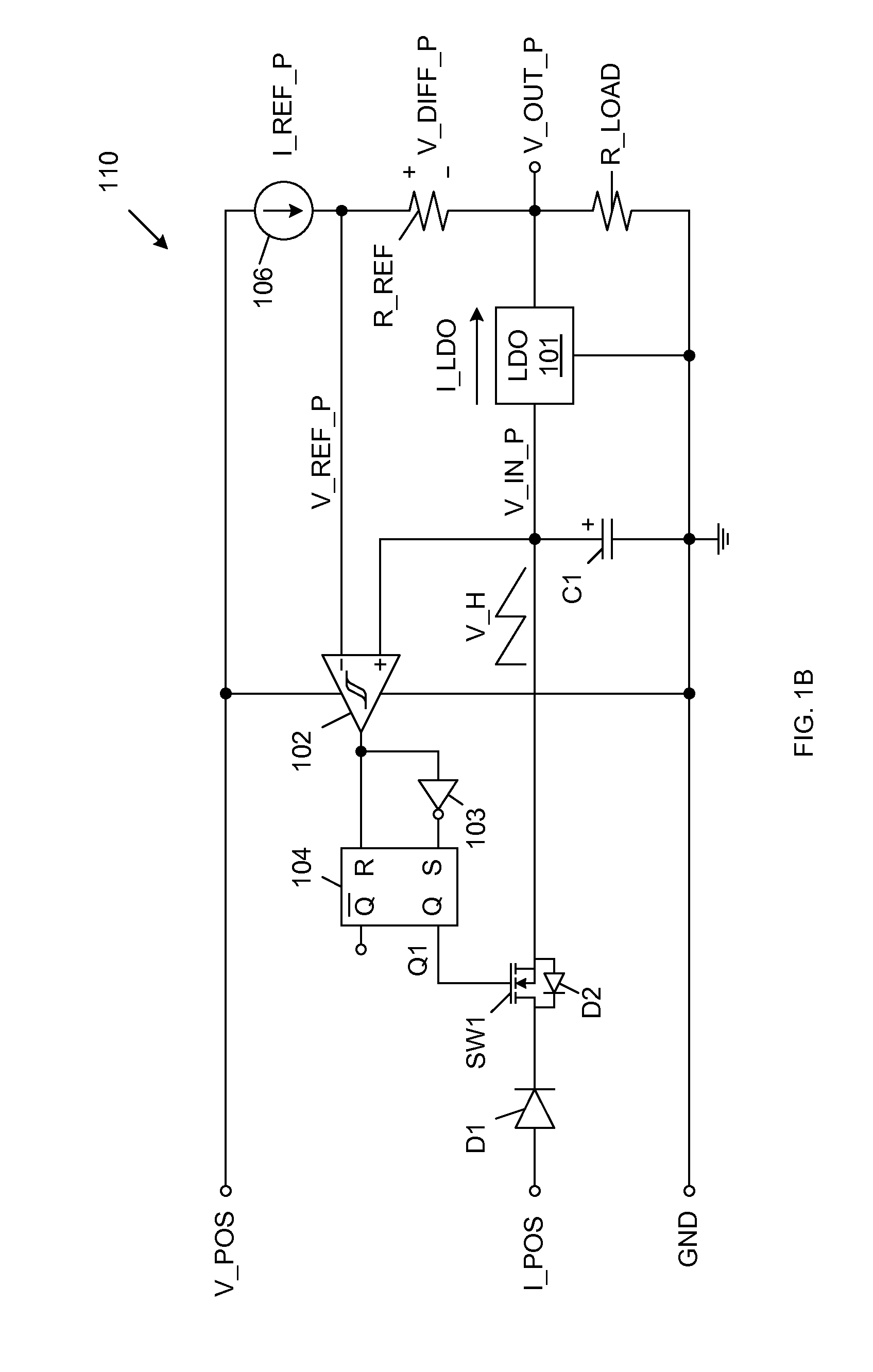
[0030]In general, the present invention provides a controlled headroom low dropout regulator (CHLDO) that includes circuitry to maximize the efficiency of a linear regulator, such as a low dropout regulator (LDO), by maintaining a very small voltage difference between the input and output terminals of the linear regulator. The CHLDO of the present invention can passively draw power from a continuous mode or discontinuous mode current source, without the need for any interactive control methodology. In alternate embodiments of the present invention, the CHLDO may either be un-clocked or clocked. The un-clocked CHLDO, which does not operate directly in response to a clock signal, does not require that any data be passed to or from the associated current source. The clocked CHLDO is enabled by and operates in synchronism with the same clock signal used to control an associated PWM current source. Thus, the clocked CHLDO of the present invention includes an additional input terminal to ...


PUM


Abstract

A controlled headroom low dropout regulator (CHLDO) having an LDO with an input voltage provided by a capacitor. An incremental voltage is added to an output voltage of the LDO to create a reference voltage. The reference voltage is compared to the input voltage to determine when to couple / de-couple the capacitor with a current source. If the capacitor is coupled to the current source, the capacitor will charge only if the voltage driven by the current source exceeds the input voltage provided by the capacitor. When the input voltage developed on the capacitor exceeds the reference voltage, the capacitor is automatically de-coupled from the current source. Multiple CHLDOs can be charged from a single current source, wherein charging automatically proceeds from the lowest voltage CHLDO to the highest voltage CHLDO.

Description

FIELD OF THE INVENTION[0001]The present invention relates to a method and structure for providing several autonomous (self-regulated) efficient linear power supply outputs from a single switch-mode power supply.RELATED ART[0002]Many hand-held portable electronic devices rely on batteries to provide power. For example, a single cell of a Lithium-Ion (Li-Ion) battery provides an output voltage that typically varies between 2.75 Volts and 4.20 Volts over the usable charge lifetime of the battery. Most electronic circuits cannot operate correctly over this wide of a voltage range. Moreover, many electronic circuits require supply voltages that are free of ripple and noise. Linear audio circuits, RF circuits and timing clocks are examples of circuits that could produce errors if powered by either widely varying or noisy voltage sources.[0003]Switch-mode power supplies have been used to stabilize the voltages provided to electronic circuits. Such switch-mode power supplies generate an out...

Claims


Application Information

Patent Timeline
Patent Type & Authority Patents(United States)
IPC IPC(8): G05F1/40H02M3/156
CPCH02M2001/007H02M3/158H02M2001/0045H02M2001/009H02M1/0045H02M1/007H02M1/009
Inventor KORZENIOWSKI, KENNETH, A.
Owner INTEGRATED DEVICE TECH INC
Why Eureka
Try Eureka