Overcurrent protection circuit
a protection circuit and overcurrent technology, applied in the direction of pulse technique, process and machine control, instruments, etc., to achieve the effect of safe semiconductor device and without reducing efficiency
- Summary
- Abstract
- Description
- Claims
- Application Information
AI Technical Summary
Benefits of technology
Problems solved by technology
Method used
Image
Examples
first embodiment
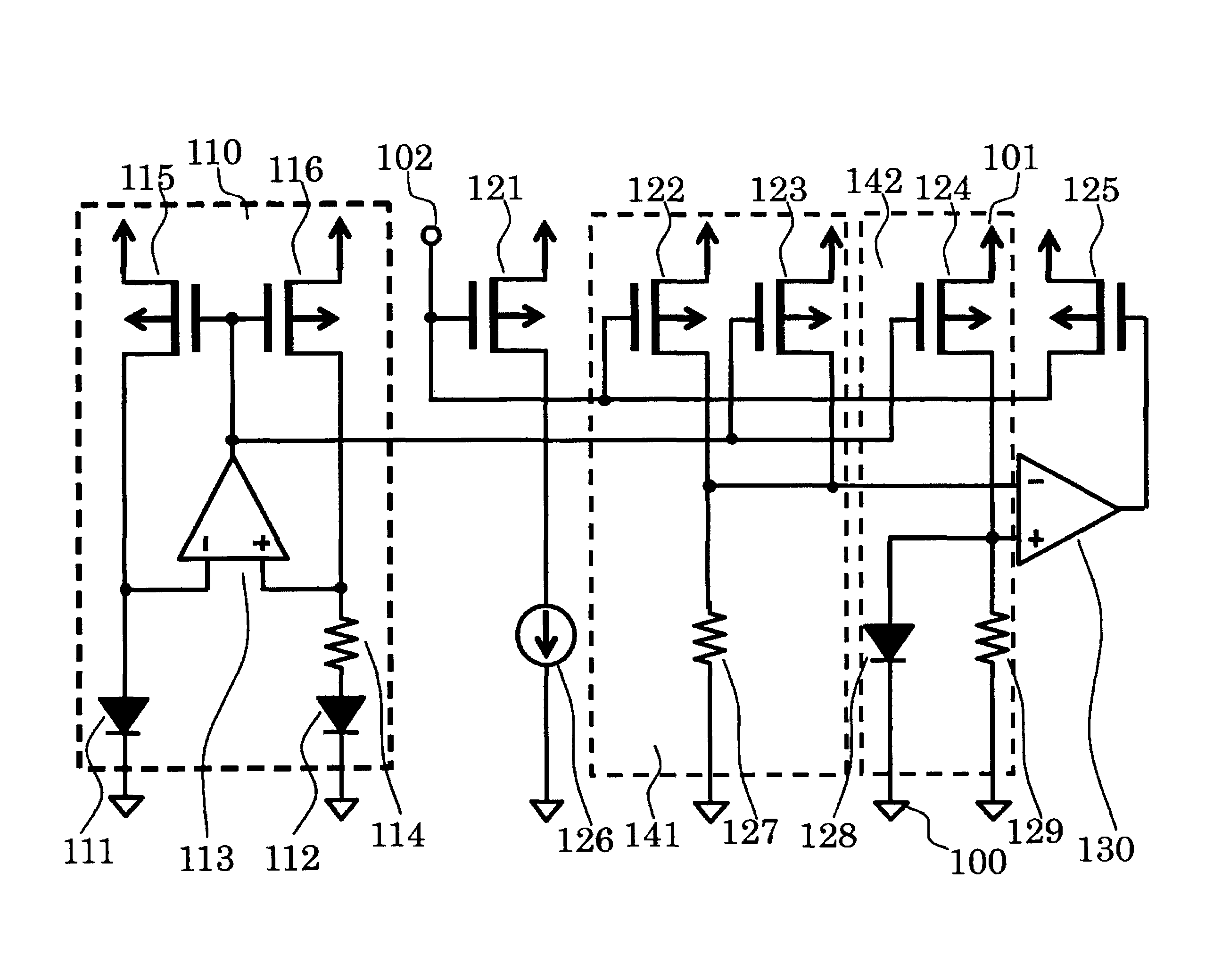
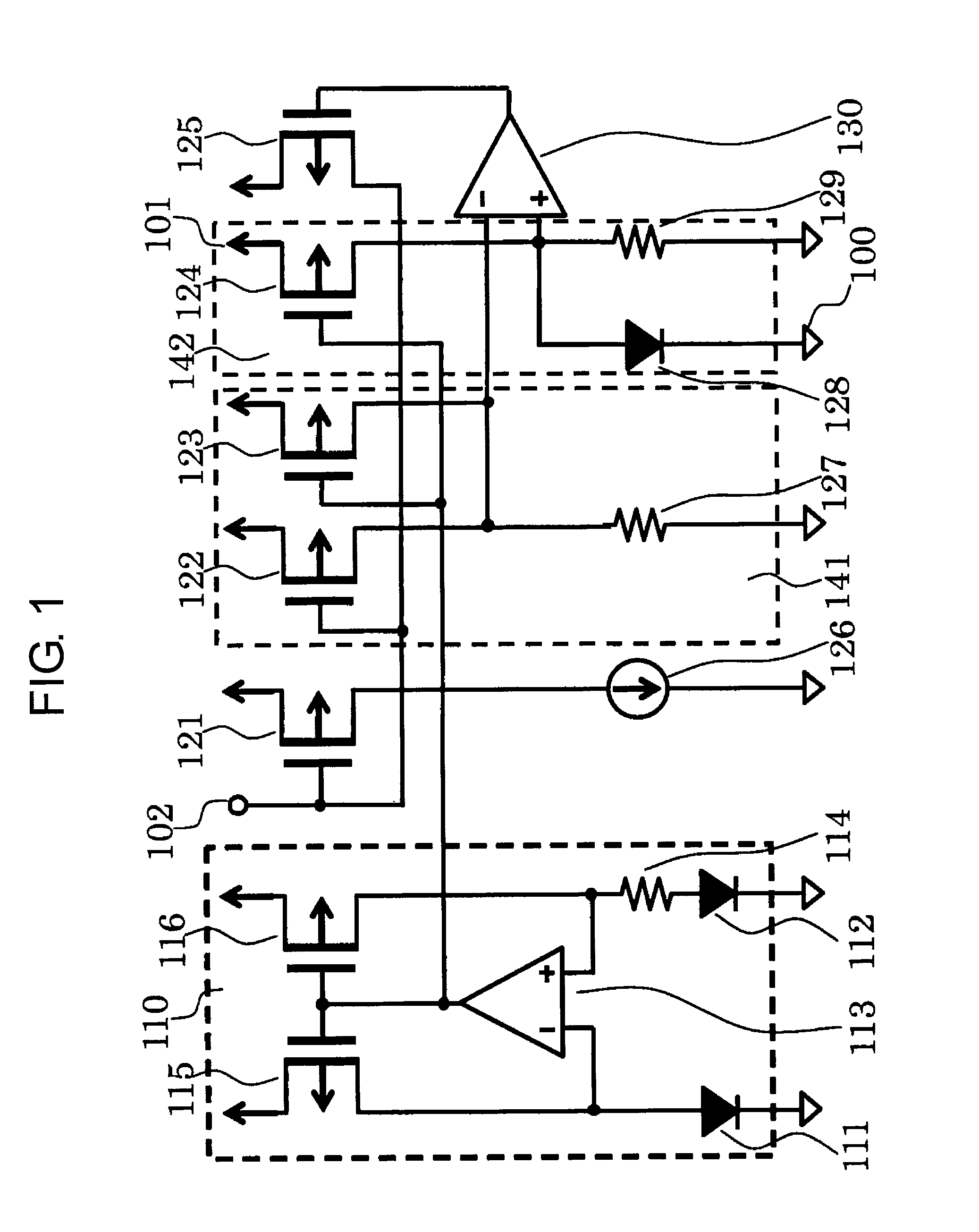
[0020]FIG. 1 is a circuit diagram of a semiconductor device according to a first embodiment of the present invention.
[0021]The semiconductor device of the first embodiment includes amplifiers 113 and 130, PMOS transistors 115, 116, 121, 122, 123, 124, and 125, a load current source 126, PN junction elements 111, 112, and 128, resistors 114, 127, and 129, a power supply terminal 101, a control terminal 102, and a ground terminal 100. The PMOS transistors 115 and 116, the amplifier 113, the PN junction elements 111 and 112, and the resistor 114 form a reference current circuit 110. The PMOS transistors 122 and 123 and the resistor 127 form a sense voltage generating circuit 141. The PMOS transistor 124, the PN junction element 128, and the resistor 129 form a reference voltage circuit 142.
[0022]Next, connection in the semiconductor device of the first embodiment is described. An inverting input terminal of the amplifier 113 is connected to a node between a drain of the PMOS transistor...
second embodiment
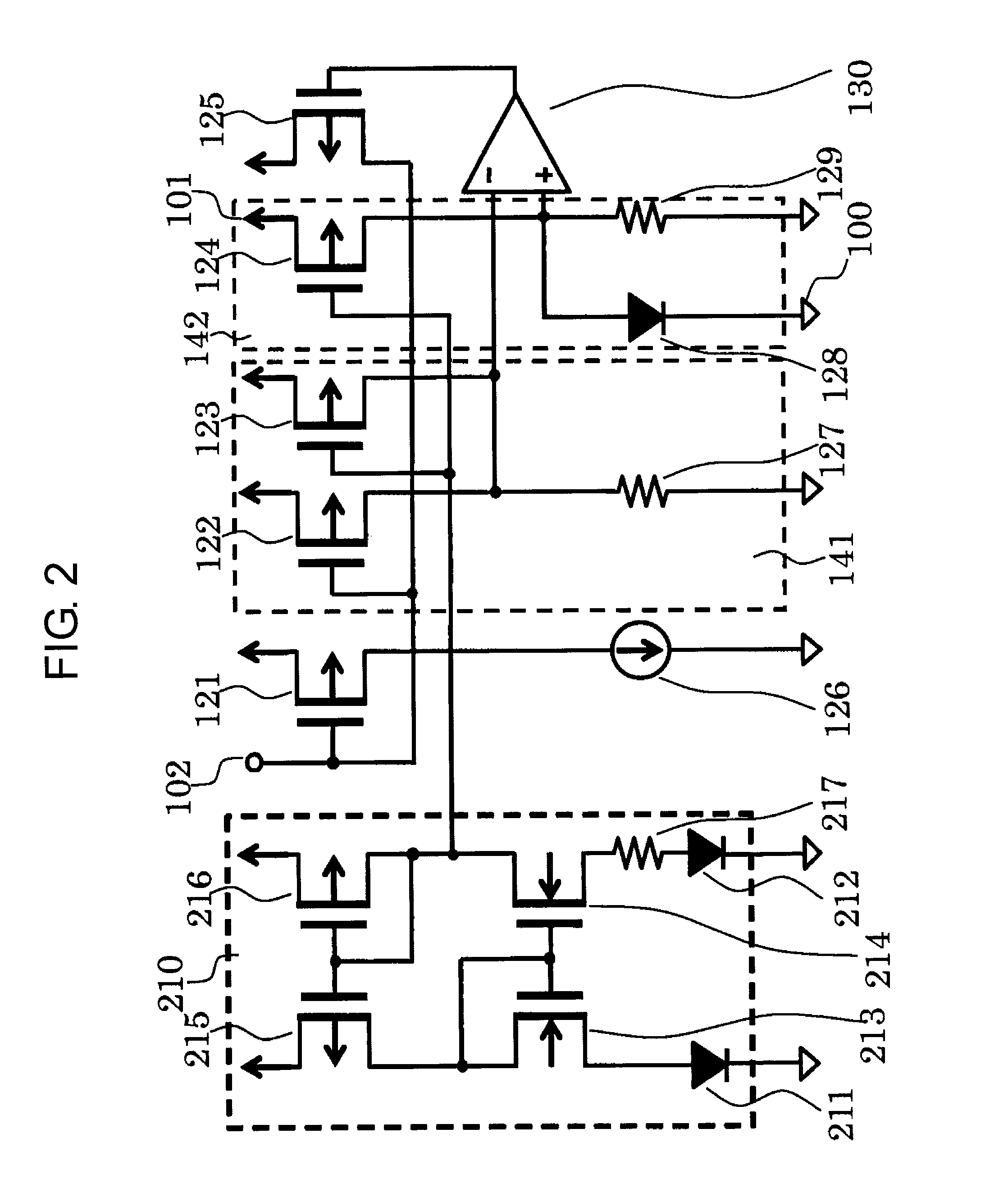
[0031]FIG. 2 is a circuit diagram of a semiconductor device according to a second embodiment of the present invention. The circuit is different from the circuit illustrated in FIG. 1 in the structure of the reference current circuit 110. In the semiconductor device of the second embodiment, PMOS transistors 215 and 216, NMOS transistors 213 and 214, PN junction elements 211 and 212, and a resistor 217 form a reference current circuit 210. Except for this point, the second embodiment is the same as the first embodiment.
[0032]Connection in the semiconductor device of the second embodiment is now described. A gate of the PMOS transistor 215 is connected to a gate and a drain of the PMOS transistor 216, a drain of the PMOS transistor 215 is connected to a gate and a drain of the NMOS transistor 213 and to a gate of the NMOS transistor 214, and a source of the PMOS transistor 215 is connected to the power supply terminal 101. A source of the PMOS transistor 216 is connected to the power ...
PUM
 Abstract
Description
Claims
Application Information
 - R&D
- Intellectual Property
- Life Sciences
- Materials
- Tech Scout
- Unparalleled Data Quality
- Higher Quality Content
- 60% Fewer Hallucinations
Browse by: Latest US Patents, China's latest patents, Technical Efficacy Thesaurus, Application Domain, Technology Topic, Popular Technical Reports.
© 2025 PatSnap. All rights reserved.Legal|Privacy policy|Modern Slavery Act Transparency Statement|Sitemap|About US| Contact US: help@patsnap.com


