Method of controlling signal generator

a signal generator and signal technology, applied in the direction of generating/distributing signals, process and machine control, etc., can solve the problems of high processing speed of microcomputers, serious problems such as biased magnetization, and increase the number of arithmetic in microcomputers, so as to achieve low operating frequency and achieve the effect of reducing efficiency

Inactive Publication Date: 2007-07-31
CANON KK
View PDF12 Cites 10 Cited by
  • Summary
  • Abstract
  • Description
  • Claims
  • Application Information

AI Technical Summary

Benefits of technology

[0024]The present invention has been devised in view of the above-described problems and it is, therefore, an object of the present invention to provide a signal generator that uses a small and inexpensive microcomputer having a low operating frequency and can perform high-frequency switching on a semiconductor device without reducing efficiency and a method of controlling a power converter using the signal generator.

Problems solved by technology

However, the conventional controlling method causes the following problem: in the power converter for photovoltaic power generation, feedback control using an output current value is performed as shown in FIG. 13 and thus an arithmetic quantity is increased in the microcomputer.
Such a signal waveform dropout may generate noise from a transformer connected to the subsequent stage of the switching element or may cause a time period when voltage is applied only to one side of the transformer.
Particularly, since a waveform dropout frequently occurs when a duty ratio increases, biased magnetization arises a serious problem.
However, the microcomputer has to have high processing speed.
Since the high-speed microcomputer is expensive with a high power consumption, a power converter has low efficiency, a higher temperature, and a large peripheral circuit.
Particularly when power converters are manufactured with small sizes and capacities, disadvantageous conditions are imposed.
In this method, the ON period of the switching element is shortened and thus a power cannot be fed sufficiently to the output side.

Method used


Image

  • Method of controlling signal generator
  • Method of controlling signal generator
  • Method of controlling signal generator

Examples


embodiment 1

(Internal Structure of Power Converter)

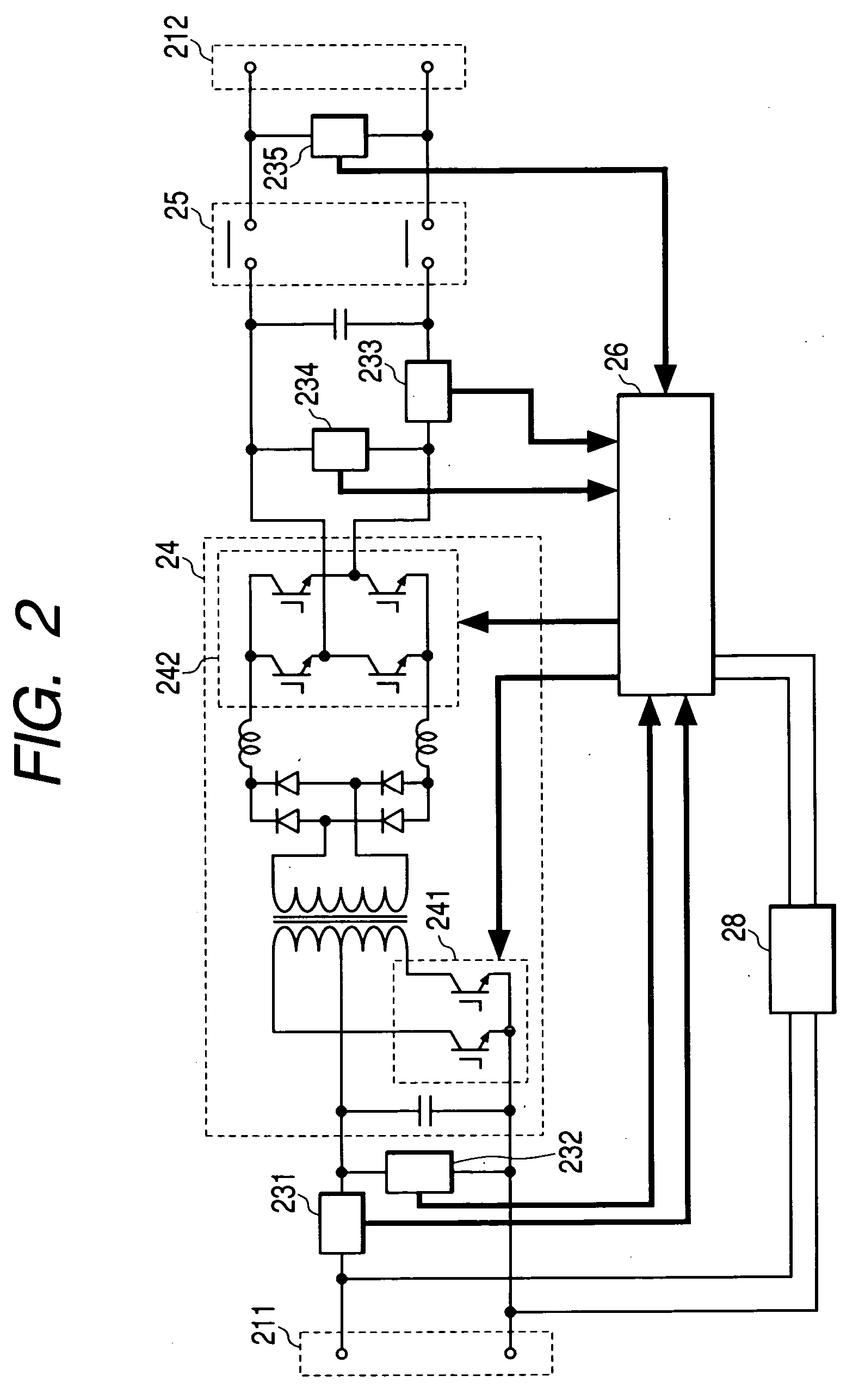
[0051]FIG. 2 shows the structure of a power converter using a signal generator of the present invention. Reference numeral 211 denotes an input terminal for inputting a direct-current power from a solar cell and reference numeral 212 denotes an output terminal for outputting a power having been converted to alternating current power to a system and an alternating load. Reference numeral 24 denotes a DC / AC converter circuit constituted of a smoothing capacitor, a reactor, a switching element and so on. Reference numeral 25 denotes an interconnection relay for opening and closing an alternating output, reference numeral 232 denotes an input voltage detector for detecting voltage inputted from the input terminal, reference numeral 231 denotes an input current detector for detecting inputted current, reference numeral 234 denotes an output voltage detector for detecting voltage which is subjected to DC / AC conversion by the DC / AC converter circuit a...

embodiment 2

[0066]Embodiment 2 of the present invention will be discussed below.

[0067]Since the internal structure and the control circuit of a power converter are the same as Embodiment 1, the following will only discuss a method of controlling a push-pull section.

(Controlling Method)

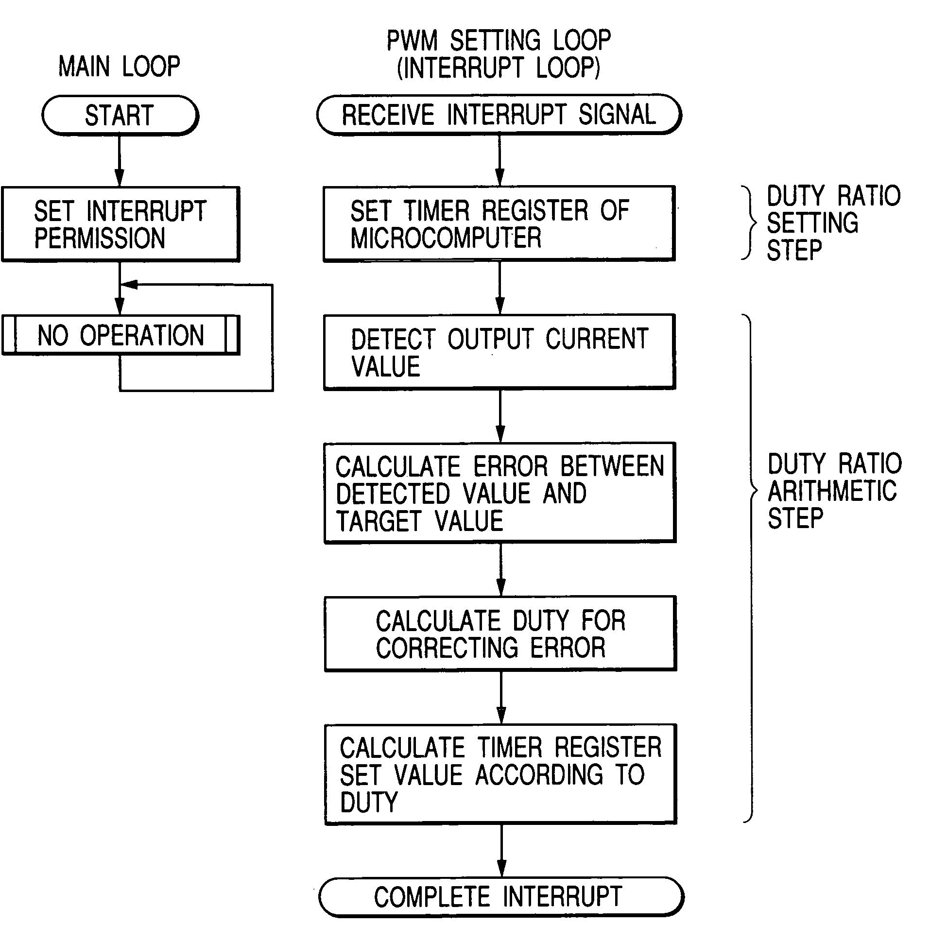
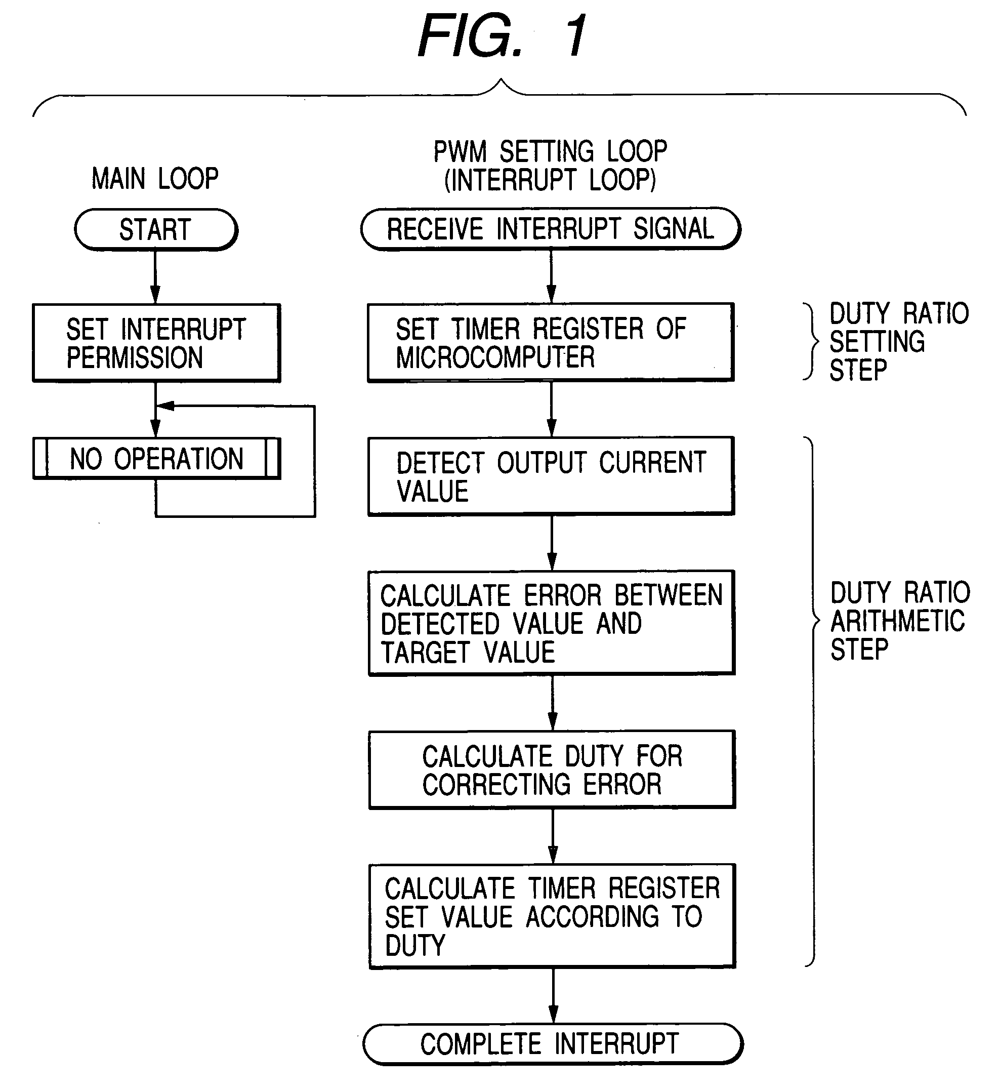
[0068]PWM control on the push-pull section is performed according to the flow of FIG. 10.

[0069]A loop for setting writing (PWM setting loop) on a timer register for controlling the push-pull section is started when an interrupting signal is inputted to a microcomputer. In this example, the values of TIMR2 and TIMR4 are fixed and the values of TIMR1 and TIMR3 are changed so as to generate a PWM control waveform. Then, only for the set value of TIMR1, a set value is used which is determined in an interrupting step before a predetermined period. A detailed flow will be discussed below.

[0070]First, an instantaneous current detection value is read which has been converted to digital data by an AD converter in the micro...

embodiment 3

[0074]Embodiment 3 of the present invention will be discussed below.

[0075]Since the internal structure and the control circuit of a power converter are the same as Embodiments 1 and 2, the following will only discuss a method of controlling a push-pull section.

(Controlling Method)

[0076]Embodiments 1 and 2 used PWM control for controlling a pulse width. The present embodiment will be described using FM control shown in FIG. 12, in which a frequency is controlled with a constant pulse width.

[0077]Since PWM control has a constant switching frequency, TIMR2 and TIMR4 of time registers have constant values all the time and only the values of TIMR1 and TIMR3 are changed, so that a pulse width is controlled. However, since a switching frequency is changed in FM control, it is necessary to rewrite all the values of the four timer registers. Thus, as compared with PWM control, time required for rewriting on the timer registers is nearly twice.

[0078]The following explanation will be made with...


PUM


Abstract

A method of controlling a semiconductor device using a microcomputer having a timer is provided. An interrupting step interrupts the semiconductor device using the timer, by generating a control signal for controlling a timing of turning on/off the semiconductor device. The interrupting step is performed in accordance with an interrupting signal which is input to the microcomputer at every occurrence of a predetermined period. The interrupting step comprises a setting step of giving a set value to the timer and a calculating step of determining a set value for a subsequent interrupting step, such that the set value determined in the calculating step is given to the timer in the setting step of the subsequent interrupting step. Therefore, a longer time can be allowed for determining a set value for the timer, and the processing speed required for the microcomputer can be reduced.

Description

BACKGROUND OF THE INVENTION[0001]1. Field of the Invention[0002]The present invention relates to a method of controlling a signal generator that uses a microcomputer having a timer and turns on / off a semiconductor device by means of the timer.[0003]2. Related Background Art[0004]There have hitherto been known various signal generators for switching semiconductor devices.[0005]Particularly, microcomputers having timers are capable of switching semiconductor devices at higher frequency than the operating frequencies of the microcomputers because the timers operate in parallel with the programs of the microcomputers and signals are outputted from I / O ports.[0006]Such microcomputers having timers are used to control various semiconductor switches. Typically, such a microcomputer controls the semiconductor main SW circuit of a power converter or a semiconductor circuit in a motor drive for a camera or a VTR.[0007]As a representative example of controlling the turning on / off of a semicond...

Claims


Application Information

Patent Timeline
Patent Type & Authority Patents(United States)
IPC IPC(8): G06F1/04G05F1/67G06F1/26H02M7/48H03L5/02
CPCH02M7/4807H02M7/53873H03L5/02
Inventor KOBAYASHI, TAKUMATAKEHARA, NOBUYOSHI
Owner CANON KK
Why Eureka
Try Eureka