Flash photolysis system

a flash photolysis and flash technology, applied in the field of laser flash photolysis, can solve the problems of large footprint, high cost of amplified femtosecond lasers, and inability to meet the energy requirements and achieve the effect of lowering the energy requirement of pump and probe light sources

Active Publication Date: 2014-05-13
GUSEV ALEX
View PDF15 Cites 3 Cited by
  • Summary
  • Abstract
  • Description
  • Claims
  • Application Information

AI Technical Summary

Benefits of technology

[0011]A LFP system for performing laser flash photolysis have been surprisingly developed and are adapted to substantially lower the energy requirement of a pump and probe light source. The LFP system includes a probe light source, a pump light source adapted to produce light pulses with nanojoule or higher level energy, a delay generator, an optical modulator, and a detector.

Problems solved by technology

The delay of the probe beam is incrementally increased over a desired time interval.
The pump beam energy in such experimental setups is often limited to several microjoules.
However, in order to generate a super-continuum in bulk materials such as sapphire one needs to have laser pulses with high peak power (MegaW), which can be produced by only a limited number of lasers including amplified femtosecond lasers.
Such amplified femtosecond lasers are expensive and have a large footprint (8-10 ft2).

Method used


Image

  • Flash photolysis system
  • Flash photolysis system
  • Flash photolysis system

Examples


Embodiment Construction

[0016]The following detailed description and appended drawings describe and illustrate various exemplary embodiments of the invention. The description and drawings serve to enable one skilled in the art to make and use the invention, and are not intended to limit the scope of the invention in any manner. In respect of the methods disclosed, the steps presented are exemplary in nature, and thus, the order of the steps is not necessary or critical.

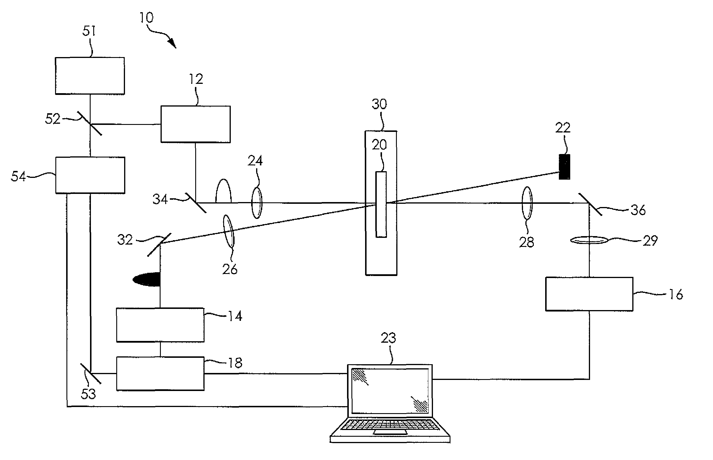
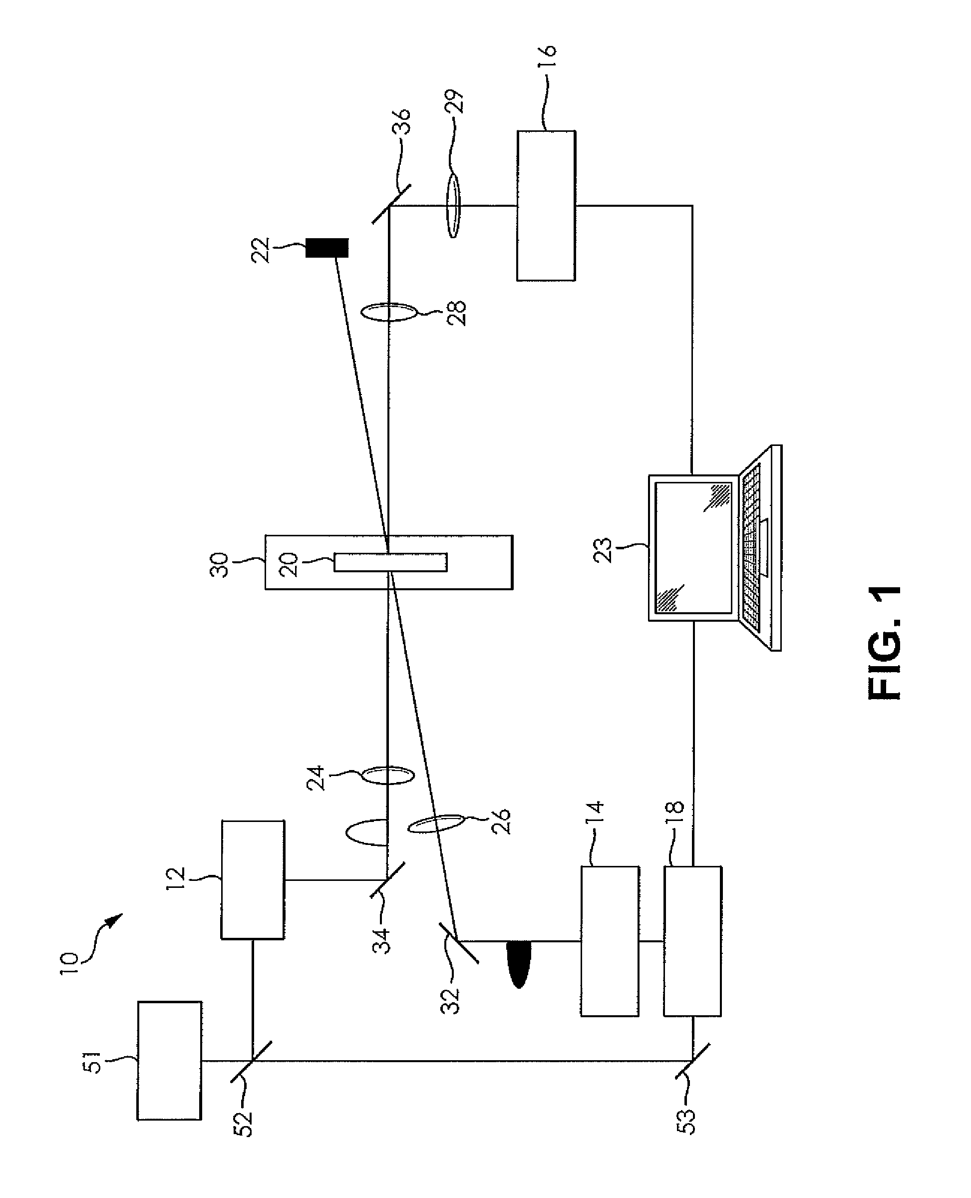
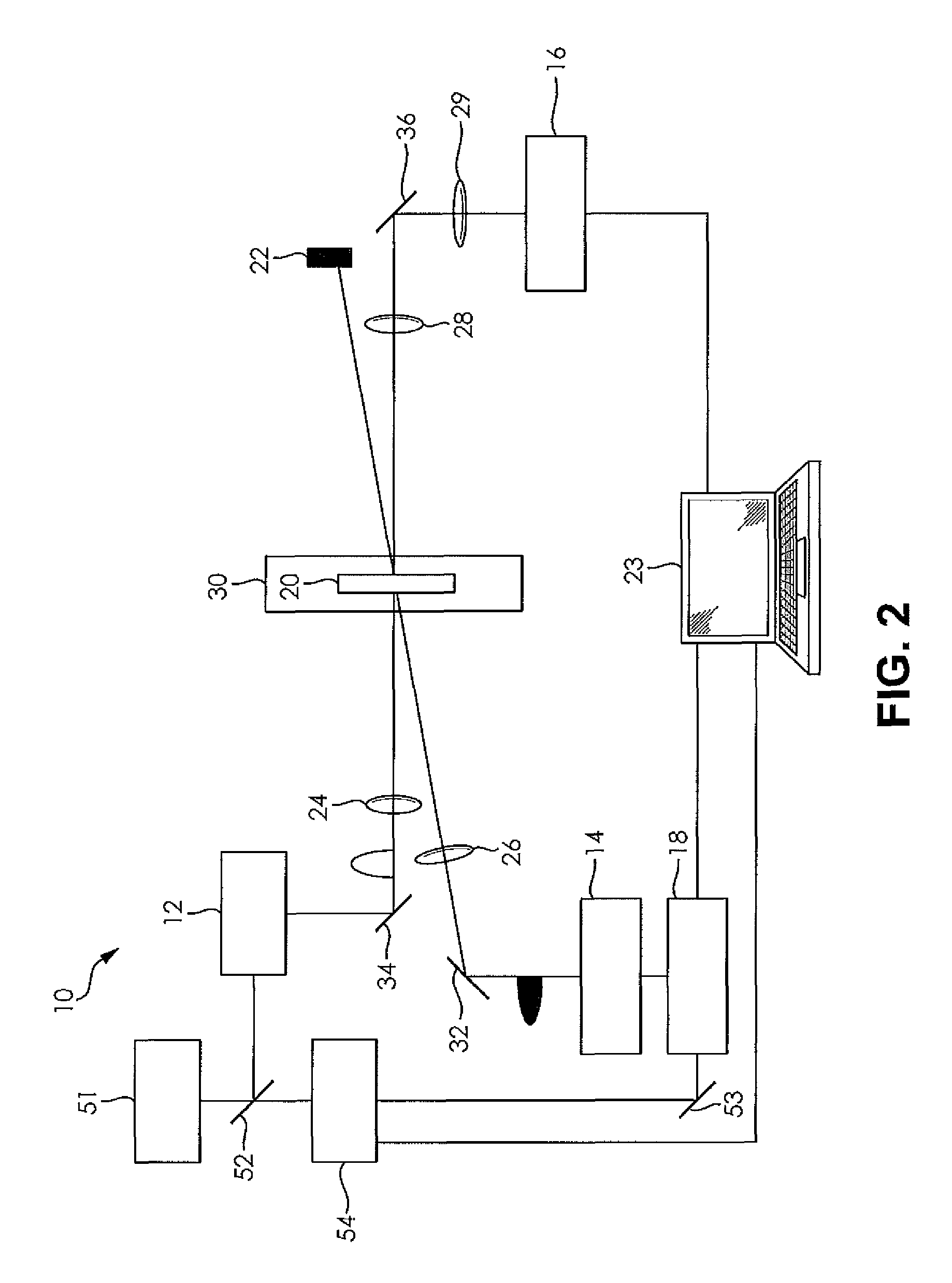
[0017]Referring to the figures, each illustrates an LFP system 10 which includes a probe light source 12, a pump light source 14, a detector 16, and a delay generator 18. The probe light source 12 shown is a photonic crystal fiber pumped by a laser 51. The probe light source 12 is adapted to be focused to areas as small as several square microns and can be focused to areas than about 1 square micron. It is understood that the probe light source 12 may be any conventional probe light source that is adapted to be focused in such manner, such a...


PUM

PropertyMeasurementUnit
areaaaaaaaaaaa
areaaaaaaaaaaa
areaaaaaaaaaaa

Abstract

A pump-probe LFP system is adapted to a substantially lower energy requirement of a pump light source and a probe light source. The LFP system includes a photonic crystal fiber based probe light source, a pump light source adapted to produce light pulses with nanojoule or higher energy, a main laser source to generate a first beam portion to the probe light source and a second beam portion to the pump light source, a delay generator, computer, an optical modulator, and a detector. One or more lenses can be used to focus the light beams to areas less than about 1 micron on a sample, where the sample can be rastered to provide domain specific flash photolysis data of the sample.

Description

CROSS-REFERENCE TO RELATED APPLICATIONS[0001]This application is a continuation-in-part of U.S. application Ser. No. 13 / 210,632, filed on Aug. 16, 2011. The entire disclosure of the above application is incorporated herein by reference.FIELD OF THE INVENTION[0002]The present invention relates to the field of laser flash photolysis and more particularly to a flash photolysis system with improved performance over existing flash photolysis spectrometers.BACKGROUND OF THE INVENTION[0003]This section provides background information related to the present disclosure which is not necessarily prior art.[0004]Laser flash photolysis (LFP) is a technique utilized to study reaction mechanisms in chemical and biological processes. The technique was introduced in 1966 by Lindqvist at the CNRS in France and the technique was quickly developed by various research groups around the world. LFP was brought about by the invention of the laser in the early 1960s. The technique of LFP consists of a pulse...

Claims


Application Information

Patent Timeline
Patent Type & Authority Patents(United States)
IPC IPC(8): G01N21/00
CPCG01N21/631G01N21/59G01N2021/1791G01N21/636
Inventor GUSEV, ALEX
Owner GUSEV ALEX
Why Eureka
Try Eureka