
Board assembly

a technology of assembly and boards, applied in the field of boards, can solve the problems of not being able to provide a mechanical connection between boards, not being able to easily disassemble, and being able to create strong mechanical connections, etc., and achieve the effects of reducing manufacturing costs and equipment investment, stable quality, and convenient assembly

Active Publication Date: 2014-05-20
HONG KONG MEI LI SHENG FLOORING +1
View PDF62 Cites 28 Cited by
  • Summary
  • Abstract
  • Description
  • Claims
  • Application Information

AI Technical Summary

Benefits of technology

The invention provides a new type of board that reduces manufacturing costs and equipment investment while still being of stable quality. The board is easy to assemble, versatile in use, and less susceptible to water damage. The board has a frame, a filler board, and an upper decorative material, all securely connected together. The filler board provides sufficient support while also being flexible to conform to uneven surfaces. Compared to existing techniques, the invention has lower manufacture costs and equipment investment. The decorative material can be chosen based on need and can be a sheet of flooring material. The filler board used in the invention has been found to provide enough support while also being flexible to conform to uneven surfaces. Overall, the invention results in a versatile and stable assembly that is easy to assemble and use.

Problems solved by technology

Problems with this system include the fact that in order to have sufficient room to form a machined vinyl locking tongue and locking groove on opposite edges of the board, the board is required to be quite thick, and vinyl itself is a relatively flexible and deformable material, not well-suited for creating a strong mechanical connection.
However, these systems do not provide a mechanical connection between boards, they cannot be readily disassembled, and are difficult to install, because once a board is placed on the joining adhesive strip, it is difficult to re-locate.

Method used


Image

  • Board assembly
  • Board assembly
  • Board assembly

Examples


example

[0071]An embodiment of the floor board described herein was tested for its acoustic properties. The embodiment was of the design of the third embodiment as described above in relation to FIGS. 10-14—this is described as “Embodiment 3” in the results tables below. The frame in the Embodiment 3 tested was made of injection moulded high impact polystyrene, with all latch tongues integrally formed with the sides of the frame, and all recesses formed in the underside of the frame. The filler board was a sheet of non-foamed PVC having a 3.6 mm thickness, the same as the thickness of the frame. The upper material was that of a Luxury Vinyl Tile material, and had four layers of calendared PVC, the bottom two of which had been stretched and allowed to relax, each having the directionality of stretching at 90° to the other, the second-from-top layer being a printed PVC layer, and the top layer being a transparent wear PVC layer. Together, the four layers of calendared PVC had a total thicknes...


PUM

PropertyMeasurementUnit
temperatureaaaaaaaaaa
Young's modulusaaaaaaaaaa

Abstract

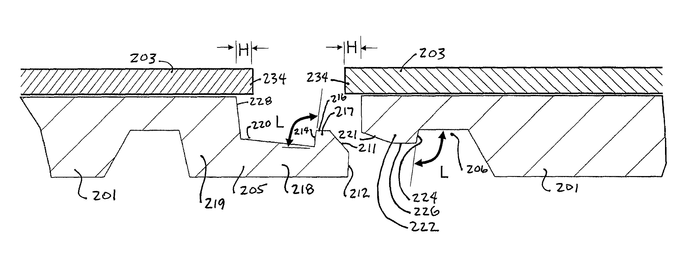
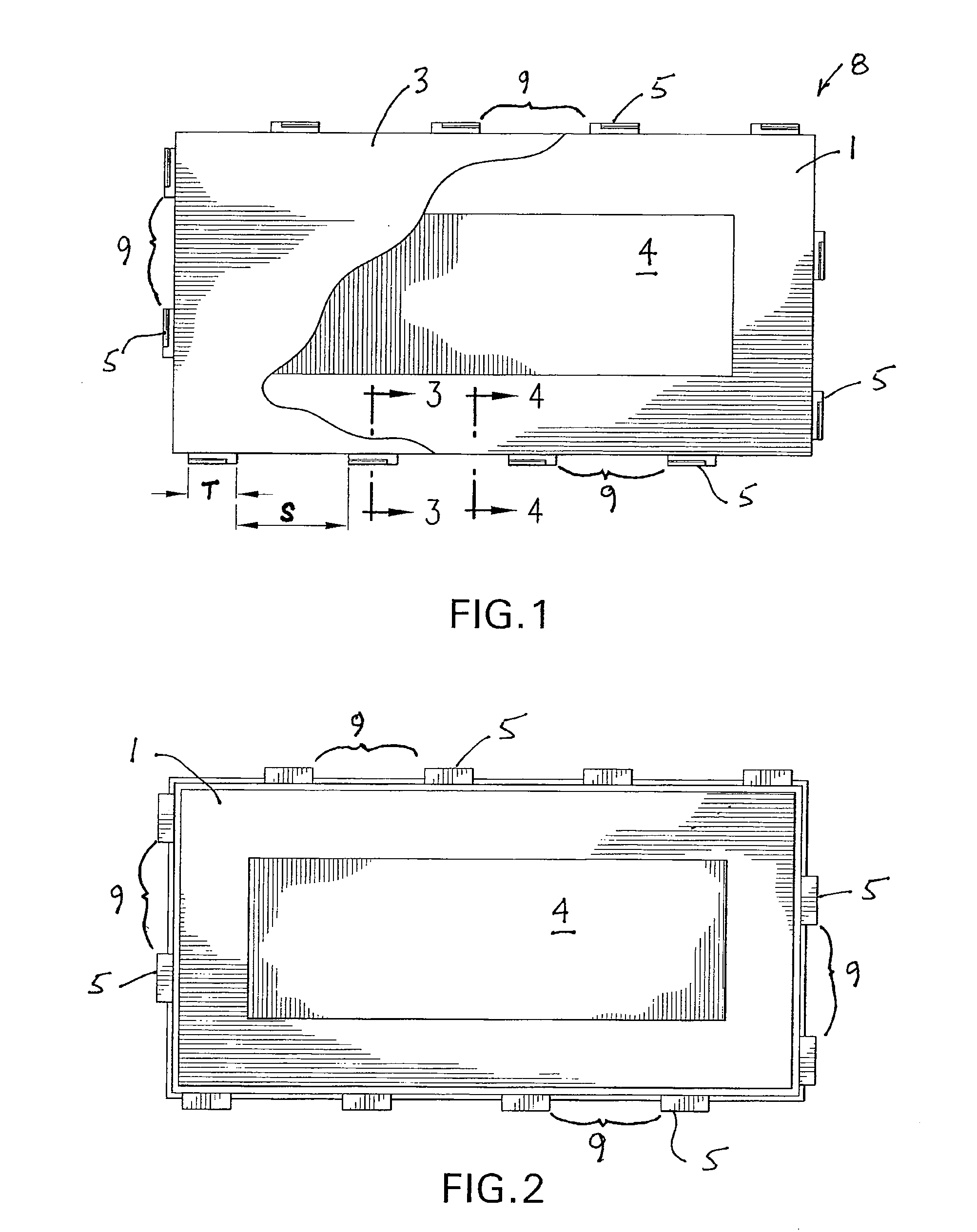
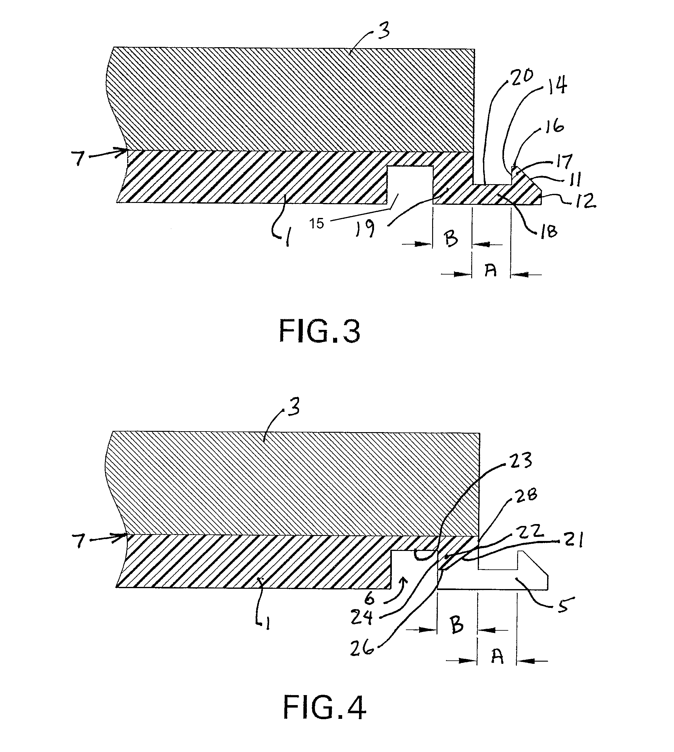
A floor board assembly convenient to lay is characterized in that, in one embodiment, it comprises a frame, a filler board and an upper material with the frame and filler board affixed to the underside of the upper material. The frame includes latch tongues that extend outwardly from the lower side edges of the frame, and the tongues have locking projections that fit into recesses arranged just inside the periphery of the underside of the frame. The tongues and intervening spaces (with locking bars behind them) are space along the periphery of the board, such that any side of one board may be joined to any side of a similarly configured board. The upper material may be selected from a variety of materials, including LVT (luxury vinyl tile), carpet, high pressure laminate or other decorative material. The filler board may be selected to accomplish reduced cost, and / or improved acoustics. In other embodiments, a frame and / or upper material may be absent. The floor board assembly requires a lower manufacture cost and lower equipment investment, has stable quality, versatility and ease of installation.

Description

TECHNICAL FIELD[0001]The present invention is related to boards, such as flooring boards, wall boards and ceiling boards.BACKGROUND[0002]Board used in the construction of floors, walls and ceilings are composed of a wide variety of materials, and designed to be joined in wide variety of ways. Floor boards are often made of composite material including multiple layers of different materials. Floor boards are also joined to one another by a wide variety of structures and techniques, including standard tongue and groove connections and more complex and easy-to-use systems that employ adhesives and adhesive tape, snapping connections incorporated into board edges, angling board with interlocking edges, and overlapping edges. Many of the edges are specially designed to achieve objectives relating to strength, minimum visibility of the joint, prevention of ingress of water and dirt, durability, low cost of production and many others objectives.[0003]In the case of flooring, there are two ...

Claims


Application Information

Patent Timeline
Patent Type & Authority Patents(United States)
IPC IPC(8): E04F15/02
CPCE04F2201/0107E04F15/107E04F2201/049E04F2201/027E04F2201/095E04F15/02E04F15/02038E04F15/105E04F2201/0115E04F2201/0123E04F2201/03E04F2201/043E04C2/38E04C2/50
Inventor HUANG, HUANWEN
Owner HONG KONG MEI LI SHENG FLOORING
Learn More