Hydropower plant provided with a grating and method for operating a such

a technology of hydropower plant and grating, which is applied in the direction of sea energy generation, liquid fuel engines, tide stream/damless hydropower, etc., can solve the problem that the deviation of such external conditions does not represent a non-uniform velocity, and achieve the effect of improving the protective effect of the grating

Inactive Publication Date: 2014-05-20
CURRENT POWER SWEDEN
View PDF11 Cites 2 Cited by
  • Summary
  • Abstract
  • Description
  • Claims
  • Application Information

AI Technical Summary

Benefits of technology

[0015]By arranging the grating such that it guides the water flow in this way the water can be guided such that it has a higher velocity in those parts of the turbine where the contribution to the power generation is higher and such that the water has a lower velocity in those parts of the turbine where the contribution is lower or even negative. Thereby the total output of the turbine will be increased and consequently the over all efficiency of the plant will be corresponding higher.
[0043]In some applications a sufficient velocity distribution can be achieved for a plurality of turbines with one single grating for these. This simplifies the plant and lowers the installation costs for the grating.

Problems solved by technology

Deviations as a result of such external conditions do not represent a non-uniform velocity in the sense of the present application.

Method used


Image

  • Hydropower plant provided with a grating and method for operating a such
  • Hydropower plant provided with a grating and method for operating a such
  • Hydropower plant provided with a grating and method for operating a such

Examples


Embodiment Construction

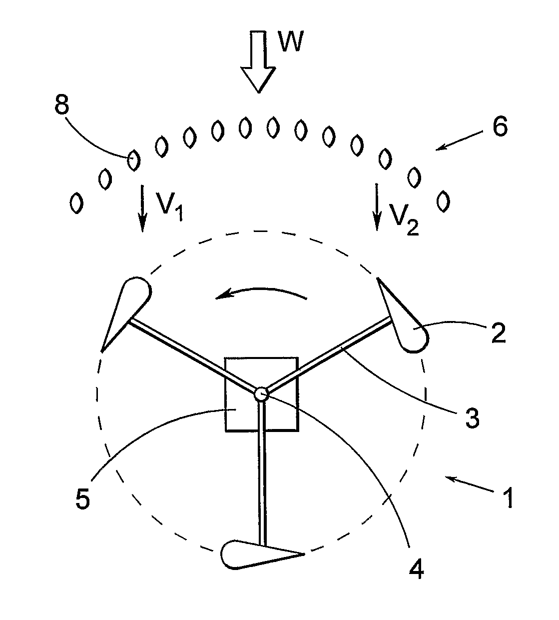
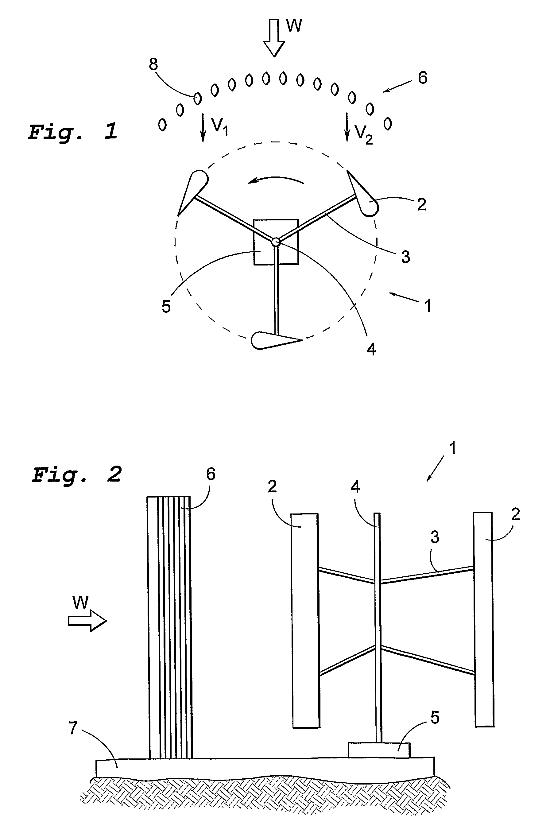
[0059]FIG. 1 in a view from above schematically illustrates a hydropower plant. The plant may consist of one single water turbine 1 as in the figure or a plurality of turbines. The turbine 1 is arranged in a water flow indicated by arrow W. The turbine has it axis mainly perpendicular to the water flow and is in the illustrated example vertically mounted. The turbine has three vanes 2 extending in parallel to the turbine axis, which vanes 2 are connected to the turbine shaft 4 via arms 3. The bottom end of the shaft 4 is connected to a generator 5. Upstreams of the turbine 1 is provided a grating 6 with vertical bars 8 to prevent objects flowing with the water to reach the turbine. As indicated by the arrow the turbine rotates in the counter-clockwise direction as consequence of the shape of the vanes 2.

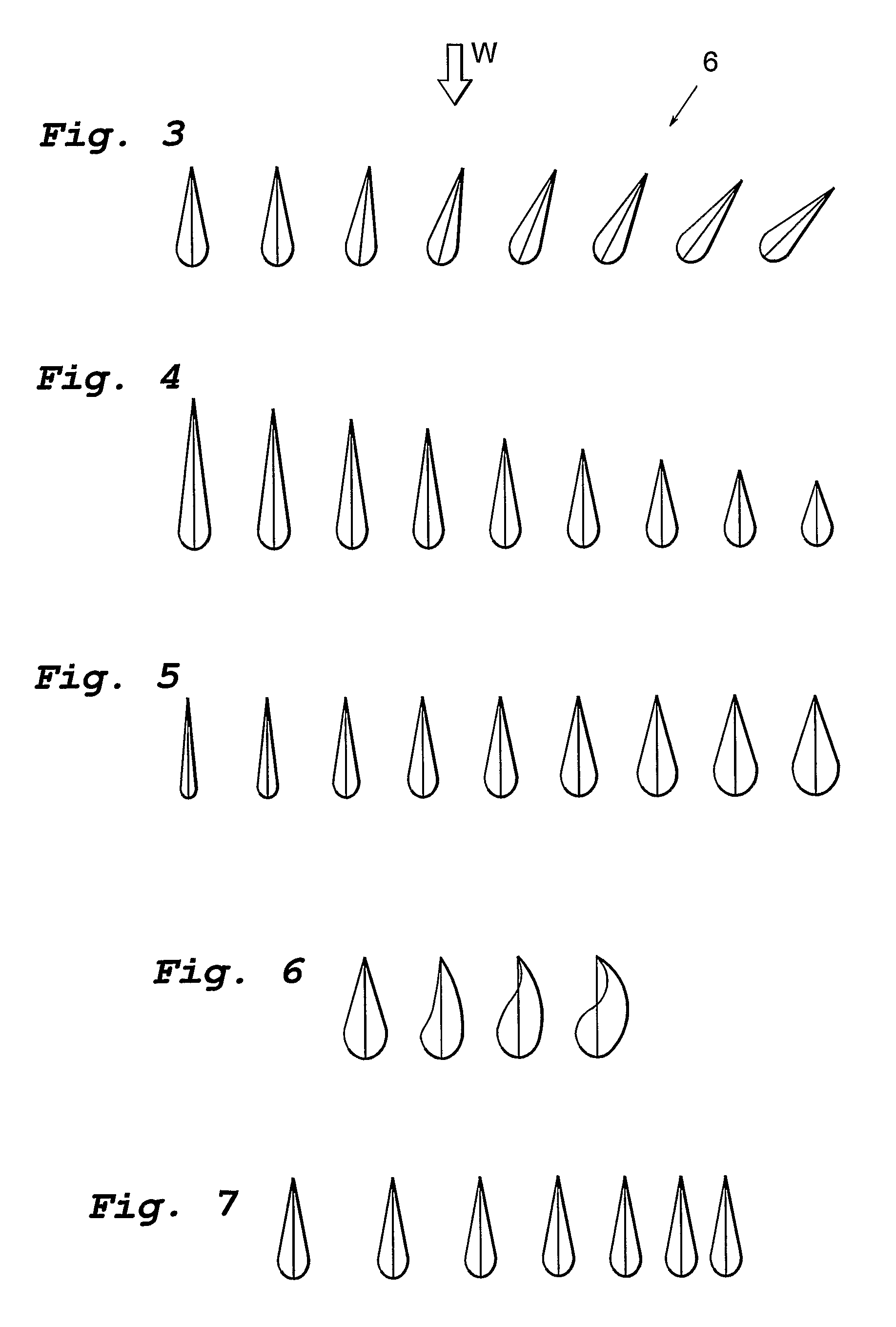
[0060]The grating 6 is designed such that it directs the water flowing through it towards that half of the turbine that creates the torque, i.e. the left side of the figure. This res...


PUM


Abstract

The invention relates to a hydropower plant including a water turbine submerged in a water current, A grating is located adjacent the water turbine. According to the invention the grating is arranged to guide the water flow in the water current such that the velocity of the water between the grating and the water turbine becomes non-uniform. The invention also relates to a use of the hydropower plant for generating electric energy for supply to an electric network. Further the invention relates to a method for operating a hydropower plant.

Description

RELATED APPLICATION DATA[0001]This application is a §371 National Stage Application of PCT International Application No. PCT / SE2008 / 050929 filed Aug. 18, 2008.FIELD OF INVENTION[0002]The present invention in a first aspect relates to a hydropower plant including at least one water turbine submerged in a water current and a grating located adjacent the water turbine.[0003]In a second aspect the invention relates to a use of such a hydropower plant.[0004]In a third aspect the invention relates to a method for operating a hydropower plant which method includes exposing a submerged water turbine to a water flow in a water course and providing a grating adjacent the water turbine.BACKGROUND OF THE INVENTION[0005]In hydropower plants it is often necessary to provide a grating upstream of is the water turbine in order to prevent objects, such as dead animals, plants, wastes etc., flowing in the water to reach the turbine. These could otherwise disturb the operation or even damage the turbi...

Claims


Application Information

Patent Timeline
Patent Type & Authority Patents(United States)
IPC IPC(8): F03B11/08F03B13/18
CPCY02E10/38F05B2240/97Y02E10/28F03B13/264F03B17/063F05B2240/12Y02E10/30F03B3/18F03B13/10F03B13/26F03B17/06Y02E10/20
Inventor LEIJON, MATS
Owner CURRENT POWER SWEDEN
Why Eureka
Try Eureka