Control system for drilling operations

a control system and drilling operation technology, applied in the direction of drilling pipes, borehole/well accessories, survey, etc., can solve the problems of hydraulic-mechanical system, loss of production time, and lack of hydraulic power units, and achieve the effect of constant weight-on-bit and rate of penetration drilling

Inactive Publication Date: 2014-05-20
CHAN YUN TAK
View PDF30 Cites 1 Cited by
  • Summary
  • Abstract
  • Description
  • Claims
  • Application Information

AI Technical Summary

Problems solved by technology

However, tension spring / wire line arrangements must be detached from the brake lever and then re-attached between drilling intervals when making a connection of drill pipe resulting in lost production time.
However, the cost for providing a hydraulic power unit, modifications to the existing drilling rig equipment and the limited intelligence of a hydraulic-mechanical system has resulted in limited application.

Method used


Image

  • Control system for drilling operations
  • Control system for drilling operations
  • Control system for drilling operations

Examples


Embodiment Construction

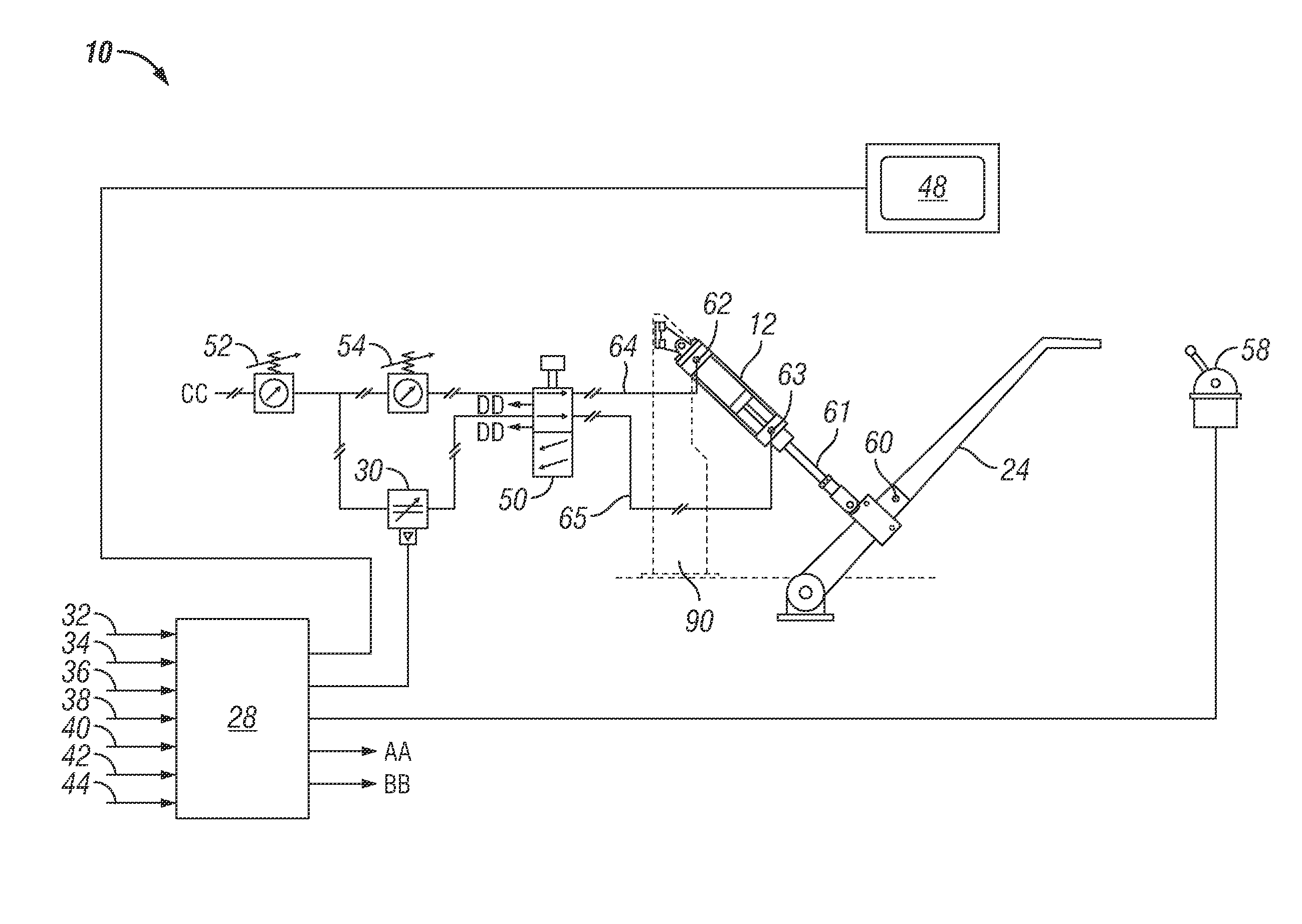
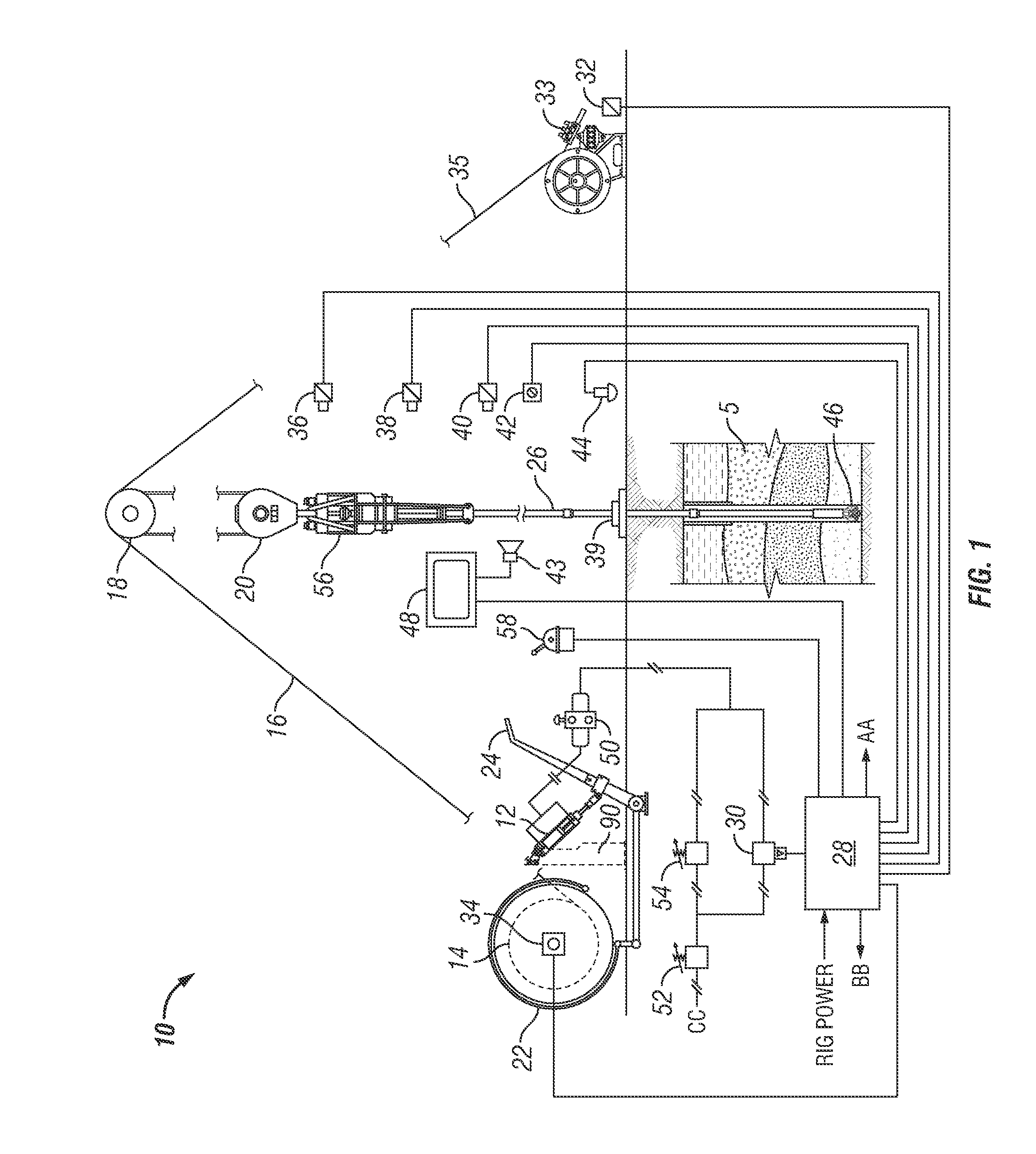
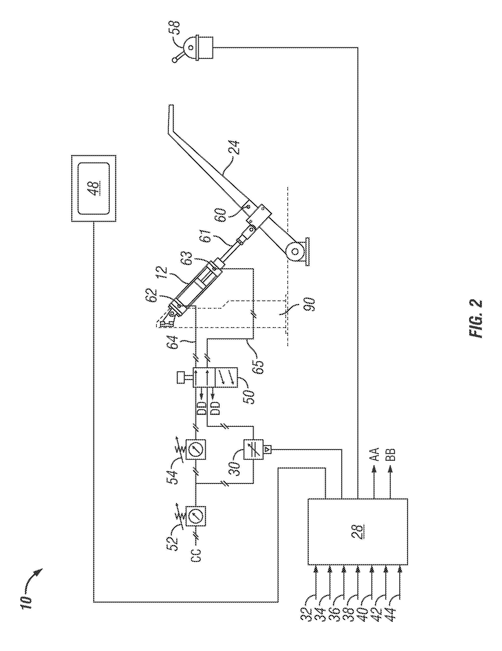
[0062]In a first non-limiting example, the present system 10 is installed on pre-existing drilling rig including band brake drawworks.

[0063]Prior to installation of the system 10, the drilling rig operated automatically using (1) a tension spring to bias the drawworks brake lever downward along a vertical plane (to apply the band brake) and (2) a wire line attached to the brake lever to raise the brake lever along a vertical plane (to release the band brake). The tension spring / wire line arrangement requires approximately one minute of time to disengage and then re-engage the tension spring and wire line to the brake lever when making a connection. In particular, when drilling to a depth of about 3048 meters (about 10,000 feet) using 111 stands (333 single joints of drill-pipe) at about 27.4 meters (about 90 feet) per stand, the total elapsed time required to disengage and then re-engage the tension spring and wire line when making connections is approximately 111 minutes, i.e., 1.8...


PUM


Abstract

The present application is directed to a system providing automatic and manual control of a brake lever on band brake drawworks of a wellbore drilling rig. The system comprises a pneumatic cylinder attached to the brake lever; and a control means in fluid communication with the pneumatic cylinder, the control means being operationally configured to run the pneumatic cylinder in response to information obtained by the control means concerning one or more drilling parameters and operationally configured to disable the pneumatic cylinder.

Description

CROSS-REFERENCE TO RELATED APPLICATIONS[0001]This application claims the benefit of previously filed U.S. provisional patent application No. 61 / 296,402, filed on Jan. 19, 2010.STATEMENT REGARDING FEDERALLY SPONSORED RESEARCH OR DEVELOPMENT[0002]Not applicable.FIELD OF THE APPLICATION[0003]The application relates generally to a system for controlling drilling operations that use band brake drawworks.BACKGROUND[0004]In drilling operations, a surface winch commonly referred to as drawworks is used to hoist a drill string via a cable whereby the drawworks is effective to payout and reel in the cable in order to raise and lower the drill string as desired. The drawworks includes a brake that controls the drill string payout to adjust the pressure applied to the drill bit suspended from the drill string against the earth formation at the bottom of a wellbore. As drilling progresses the pressure or “weight-on-bit” decreases. By releasing the drawworks brake, the weight-on-bit may be applie...

Claims


Application Information

Patent Timeline
Patent Type & Authority Patents(United States)
IPC IPC(8): E21B44/02
CPCE21B44/02E21B19/08
Inventor CHAN, YUN, TAK
Owner CHAN YUN TAK
Why Eureka
Try Eureka