Surgical stapler

a technology of surgical stapler and stapling needle, which is applied in the field of surgical stapler, can solve the problems of increased necrosis, needless reduction of blood flow to the tissue surrounding the cut-line, and decrease in the time necessary to achieve hemostasis, and achieve the effect of facilitating the manufacturing process

Inactive Publication Date: 2014-05-20
TYCO HEALTHCARE GRP LP
View PDF38 Cites 809 Cited by
  • Summary
  • Abstract
  • Description
  • Claims
  • Application Information

AI Technical Summary

Benefits of technology

[0010]The present disclosure relates to forming different sized staples by advancing cam members on different planes. In preferred embodiments, the cam members have common sizes and angles and the pushers have common sizes and angles which among other advantages, can facilitate the manufacturing process.
[0011]More specifically, a cartridge section having offset or stepped surfaces for cam members to travel along is disclosed herein. The offset or stepped surfaces allow the cam members to travel in different planes, which enables in preferred embodiments cam members of substantially the same height and pushers of substantially the same height to be used to fire staples of different sizes against an anvil.

Problems solved by technology

A common issue in transecting tissue and / or in anastomosis procedures employing the surgical stapling instruments is the balance between anastomotic strength and the degree of hemostasis achievable.
It is commonly known that by increasing the amount of pressure applied to a wound, the flow of blood can be limited, thereby decreasing the time necessary to achieve hemostasis.
Each of the fasteners will generally apply a compressive force to the tissue sufficient to effectuate hemostasis, however, if too much pressure is applied, this can result in a needless reduction in blood flow to the tissue surrounding the cut-line.
Accordingly, the joining of tissue together in this manner may result in an elevated level of necrosis, a slower rate of healing, and / or a greater convalescence.
On the other hand, if not enough pressure is applied, proper hemostasis may not be achieved.

Method used


Image

  • Surgical stapler
  • Surgical stapler
  • Surgical stapler

Examples


Embodiment Construction

[0028]Embodiments of the presently disclosed stapler will now be described in detail with reference to the drawings wherein like numerals designate identical or corresponding elements in each of the several views. As is common in the art, the term “proximal” refers to that part or component closer to the user or operator, i.e. surgeon or physician, while the term “distal” refers to that part or component further away from the user.

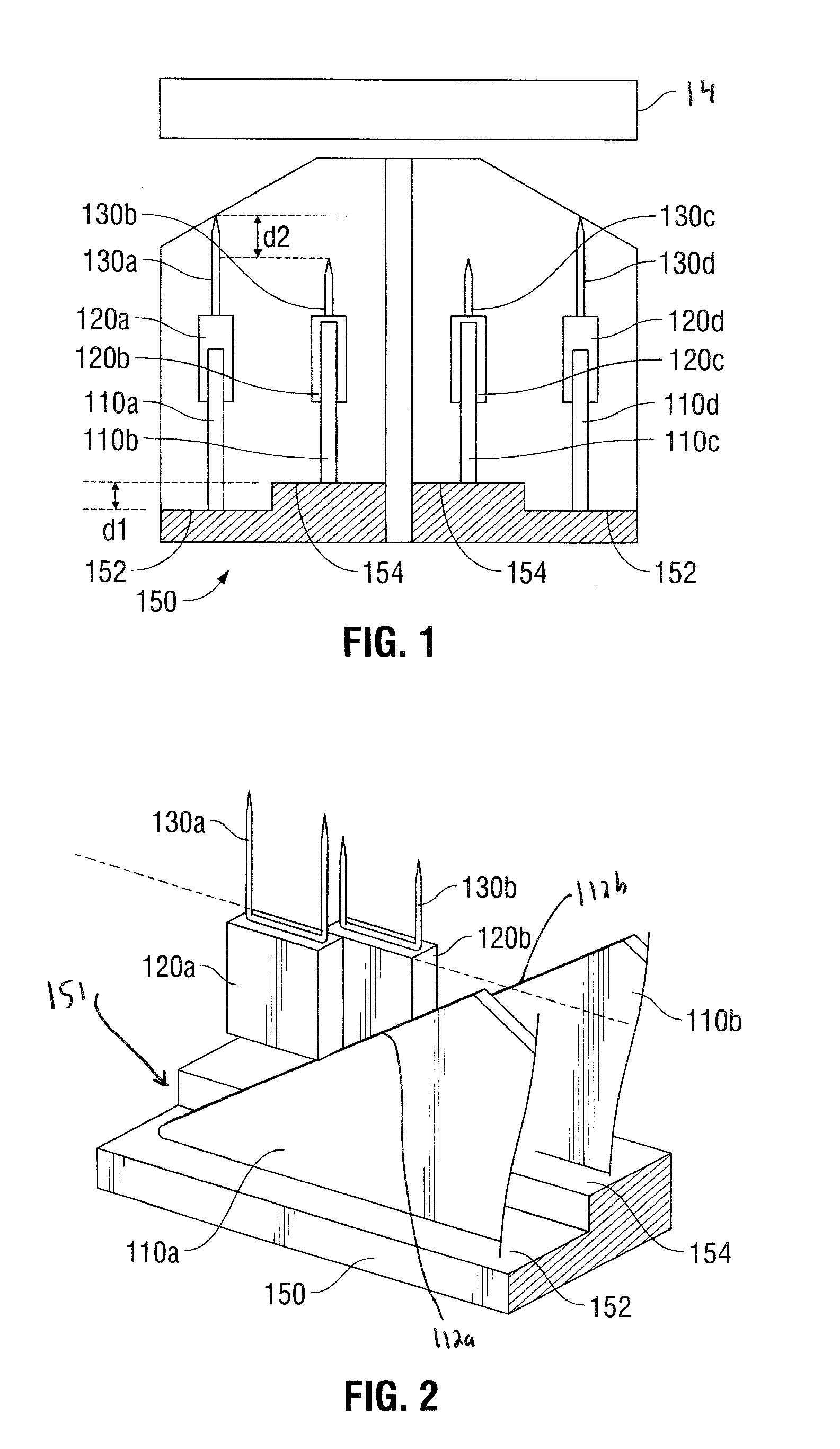
[0029]FIGS. 1 and 2 illustrate a first embodiment of the cam bar / pusher arrangement of the present disclosure. FIGS. 3 and 4 illustrate one type of surgical stapler that can incorporate the cam bar / pusher arrangement of FIG. 1.

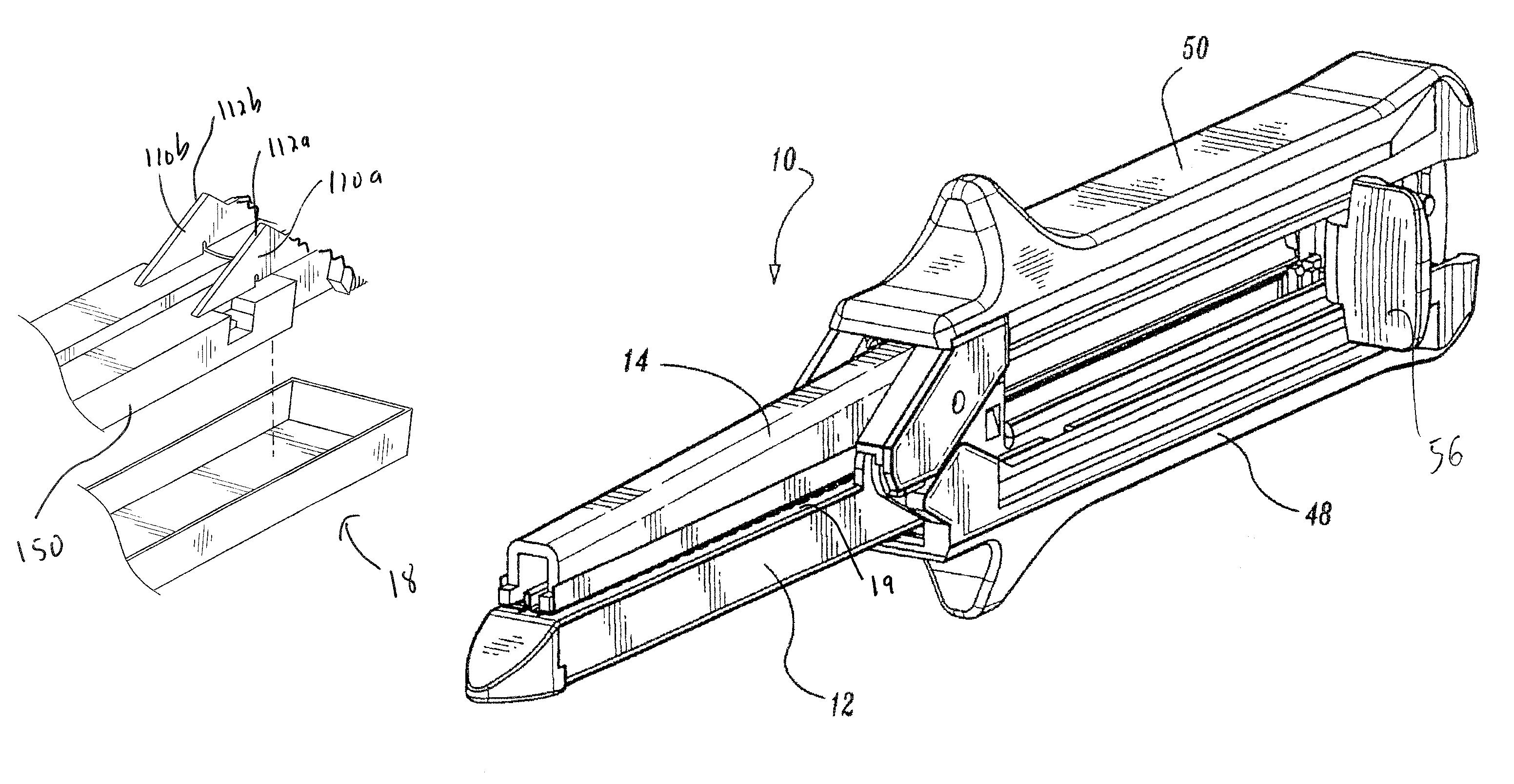
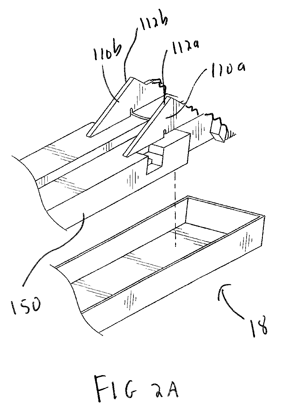
[0030]Turning first to FIGS. 3 and 4, the stapler 10 has a cartridge receiving half section 12, an anvil half section 14, and handles 48 and 50 for facilitating clamping of the sections 12 and 14. Cartridge half section 12 has a channel 18 (FIG. 2A) to receive cartridge assembly 16 which includes a plurality of staples 130 and a plur...


PUM

PropertyMeasurementUnit
heightaaaaaaaaaa
lengthaaaaaaaaaa
thicknessaaaaaaaaaa

Abstract

A surgical fastener applying apparatus comprising a cartridge section having a cartridge containing a plurality of fasteners, an anvil section having an anvil for receiving the fasteners when advanced from the cartridge, the cartridge and anvil sections clamping tissue therebetween. The first and second cam members are movable within the cartridge section to fire the fasteners. A cam member supporting member fixed within the cartridge section has an upper surface on which the cam members are slidable. The upper surface of the cam member supporting member has a first upper surface portion on a first plane and a second lower surface portion in a different substantially parallel second plane such that the first and second cam members slide in offset planes on the upper surface to fire the fasteners.

Description

[0001]This application claims priority from provisional application Ser. No. 61 / 018,685, filed Jan. 3, 2008, the entire contents of which are incorporated herein by reference.BACKGROUND[0002]1. Technical Field[0003]The present disclosure relates to a surgical stapling device and more particularly to a surgical stapling device having pusher-engaging cam members that are slidable on offset planes.[0004]2. Background of the Related Art[0005]There are several known types of surgical stapling instruments specifically adapted for use in various procedures. In many such surgical devices, tissue is first grasped or clamped between opposing jaw structures and then joined by surgical fasteners. The fasteners are typically in the form of surgical staples. These staples generally include a pair of legs adapted to penetrate tissue and connected by a backspan from which they extend. In use, the staples are formed to a “B” configuration. Two-part fasteners are also known and include legs that are ...

Claims


Application Information

Patent Timeline
Patent Type & Authority Patents(United States)
IPC IPC(8): A61B17/10A61B17/04
CPCA61B2017/07242A61B17/068A61B17/07207A61B2017/0725A61B2017/07235
Inventor WENCHELL, THOMAS
Owner TYCO HEALTHCARE GRP LP
Why Eureka
Try Eureka